|
74C14 40106 |
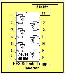 |
This chip is known by a number of identities. 74C14.
It is also marketed as 40106, 40014, and 74HC14. These are CMOS chips
and are characterised by low current consumption, high input
impedance and a supply voltage from 5v to 15v. (Do not substitute 7414 or
74LS14. They are TTL chips and operate on 4.5v to 5.5v and have low impedance
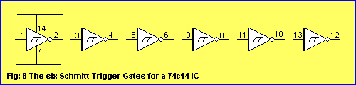
inputs.) The 74C14 contains 6 Schmitt Trigger gates. Minimum supply voltage 5v Maximum supply voltage 15v Max current per output 10mA Maximum speed of operation 4MHz Current consumption approx 1uA with nothing connected to the inputs or outputs. See Page 49 and Page 76 of Basic Electronics Course for details on how to use this chip. |
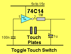
Circuits using a 74c14:
Here are the basic oscillator blocks for a 74C14 (40106) IC:
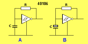
An oscillator is created by placing a
resistor from output to input and a capacitor from input to 0v.
The output will be a square-wave and and the mark (high) will be equal
to the space (low).
The frequency of the output will depend on the value of R and C. Values
of 1k to 4M7 for R and 100p to 100u for C can be used. This is shown in
circuits A and B.
If an unequal HIGH and LOW is required, a diode is placed between output
and input:
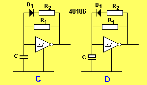
In figure C the output is output is low for a short period
of time as the two resistors R1 and R2 are discharging the capacitor. If
R2 is a very low value compared with R1 we can get the low duration to
be 10% or less, of the HIGH.
In figure D the diode is reversed compared to figure C and output is
high for a short period of time as the two resistors R1 and R2 are
charging the capacitor.
To gate the oscillator via another inverter, the following circuit is used:
When the push-button is pressed, the input of the first gate goes LOW and the output goes HIGH. The high from the diode prevents the capacitor discharging and the output of the oscillator remains LOW.
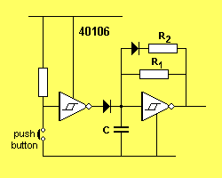
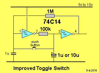
To turn the oscillator on and off, we can add the following TOGGLE circuit:
The Touch Plates can be replaced with a switch and
to keep the charge on the 100n (or to keep the capacitor discharged), a second gate is added.
This is necessary if you want to hold the state for a long period of
time.
A little-known fact is the input of the 40106 has a microscopic current
availability and over a period of a few hours it will charge the 100n
and cause the circuit to re-trigger. That's why the 4M7 is needed.
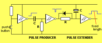
To extend the action of a push button, a pulse-extender circuit can be added:

To produce a pulse of constant length, (no matter how long the button is pressed), the following circuit is needed:
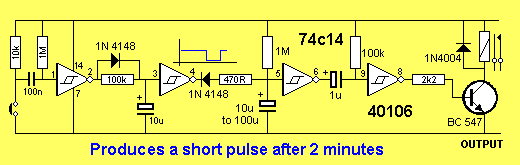
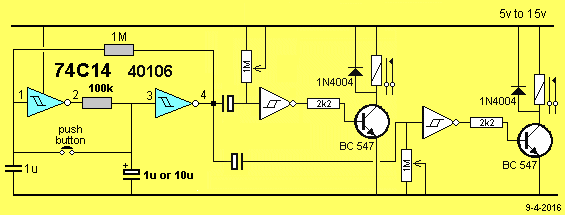
2 MINUTE TIMER
The relay is energized for a short time, 2 minutes after the push-button is pressed. The push-button produces a brief LOW on pin 1, no matter how long it is pushed and this produces a pulse of constant length via the three components between pin 2 and 3.
This pulse is long enough to fully discharge the 100u timing electrolytic on pin 5.
The 100k and electrolytic between pins 6 and 9 are designed to produce a brief pulse to energize the relay.
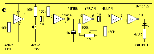
Here is another very similar circuit. Use either the active HIGH or Active LOW switch and if the Active LOW switch is used, do not connect the parts or gate between pins 1 and 2 to the rest of the circuit.
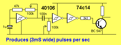
The 74c14 can be used for lots of different circuits. In the following design, the output produces 3mS pulses every second. The circuit is adjustable to a wide range of requirements.
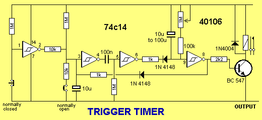
TRIGGER TIMER
The next design interfaces a "Normally Open" and "Normally Closed" switch to a delay circuit.
The feedback diode from the output prevents the inputs re-triggering the timer (during the delay period) the so that a device such as a motor, globe or voice chip can be activated for a set period of time.
TOGGLE TWO ITEMS
This circuit will turn on the first relay for a
short period of time when the push button is momentarily pressed
and released.
When the item has turned OFF, the other relay will be energised
for a short period of time after the button is pressed. Both
relays cannot be turned ON at the same time.
20-3-2016