|
|
BASIC
ELECTRONICS COURSE
Page 45  INDEX
INDEX

INTERFACING
TO GATES
In this section we show how to connect
input devices to gates. You cannot simply connect an input device such as
coil or microphone or photo-diode or photo-transistor to a gate and expect
it to work.
The reason is the INPUT DEVICE has a very small voltage swing (i.e: from one
state to the other - such as the OFF state to the ON state) and this is not
sufficient to change the gate.
A gate (such as those we covered on page
26), requires a voltage change of
30% or MORE of rail voltage for the output to change from one state to the
other.
We need a VOLTAGE AMPLIFIER between the input device and the gate. This
amplifier is called an INTERFACE or INTERFACE DEVICE.
In reality it can be a single transistor (called a SINGLE TRANSISTOR STAGE)
but there are two criteria that need to be met:
1. The stage must be able to swing nearly 100% (of rail voltage).
2. The stage must change from one state to the other VERY QUICKLY (many
gates start to "self oscillate" if the input voltage does not pass
mid-rail-voltage VERY QUICKLY - in other words the gate oscillates ALL BY
ITSELF and causes the output to go high-low very quickly. This causes the
chip to consume a lot of power and it can heat up. This is something we must
avoid and that's why the input line must NOT be allowed to sit at mid-rail).

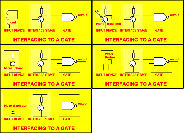
The animation above shows an input device needs to be connected to a gate
via an INTERFACE STAGE.
However you cannot connect them together without determining:
1. If a capacitor is required between the input device and the Interface
Stage.
2. The biasing of the Interface Stage - to suit the input properties of the
GATE. The second requirement is the easiest to satisfy as all
gates have the same input requirement.
Basically it is
this:
A. The input line must swing at least
80% of rail voltage. This means the waveform must go down to 10% of rail
voltage and up to 90% of rail voltage.
PLUS the most important feature:
B. The voltage MUST NOT sit at mid-rail and it MUST change very quickly from one
state to the other.
If the Interface Stage can satisfy these requirements, it can be
connected directly to the Gate.
A capacitor will be needed between the input device and the base if the base
voltage cannot be allowed to fluctuate between 0.5v and 0.7v. We
will start by assuming the Interface stage can be connected directly to the
input of the gate. This means the transistor will be sitting in "Cutoff"
mode (non conducting) or "bottoming" mode (fully conducting) and
it will pass from one state to the other VERY QUICKLY.
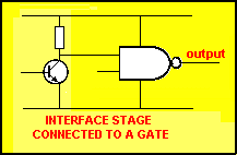
The diagram below shows the Interface
Stage connected directly to the input of the Gate.

The
transistor is connected to one input line of the gate. The other input is called the CONTROL
LINE. For a NAND gate, when it is HIGH, the Gate detects the signal from the Interface Stage and the output
responds according to the feature of the gate. (The "feature"
of the gate can be worked out from the TRUTH
TABLE found on Page 11.) For a NAND gate, when the input line
is HIGH, the output is LOW.
When the control line is LOW, the output is "FROZEN."
It may be
HIGH or LOW, according to the type of gate used. For instance, if a NOR
gate is used, the control line has to be LOW and the output will be the
opposite of the input. Normally the control
line is connected directly to either positive or negative rail so that the
gate will operate.
| Understanding this
article is very important as it also applies to
the input lines of a microcontroller. We are studying the PIC12C508A microcontroller and PIC16F84
microcontroller in our PIC Microcontroller section. |
The Interface Stage has the effect of "speeding up" the waveform.
It doesn't really speed it up but the output goes from 0v to rail volts
during the time when the waveform passes from 0.5v to about 0.7v. Since
it doesn't take very long for a waveform to pass through this voltage range,
the output of the Interface Stage goes from 0v to full rail voltage and thus
it appears to be "speeded up."
The point we have just covered is very important so we will explain it again
by saying the base of the Interface transistor only detects the voltage
between about 0.6v and 0.7v. Below 0.6v the transistor is NOT TURNED ON.
Above 0.7v, the transistor is FULLY TURNED ON.
The diagram below shows the interface stage connected to a NAND gate and NOR
gate, with the CONTROL LINE connected so that the gate operates in INVERSION
MODE:

We will take the NAND gate and connect the following
devices:
1. Coil
2. Photo transistor
3. Microphone
4. Water probes
5. Piezo diaphragm
THE COIL
In most cases a coil produces a very low output (meaning low-voltage
output). If the coil produces more than 100mV, a single transistor can be
used. If the output is less than 100mV, two stages of amplification will be
required. We will cover both cases.
The output (voltage) of a coil depends on three things:
1. The number of turns on the coil.
2. The type of magnetic material passing the coil. (this is often a magnet)
3. The speed at which the magnet passes the coil.
We will not be discussing these three characteristics but the maximum output is obtained when the coil has the maximum number of
turns, the magnet is very powerful and it passes the coil very quickly. When
we say "passes the coil," the maximum output is obtained when the
magnet passes through the middle of the coil and is as close to the coil as possible.
The typical output of a coil with say 5,000 turns and detecting the passage
of a magnet is only a few millivolts. Don't get confused with a coil that
has a collapsing current flowing through it. In this case the output can be
10 to 100 times MORE than the applied voltage and is the principle of a
SPARK COIL.
A coil that detects a magnet is called a MAGNETIC TRANSDUCER and these
generally have a very low output. That's why they need a very high-gain
circuit for their operation.
The output of a coil is a sinewave while the input to the gate must be in
the form of a square-wave. In other words, the input must rise and fall very
quickly. To convert a sinewave to a square wave is simply a matter of OVER
AMPLIFICATION. In other words, amplify the waveform as much as possible and
it will turn into a square wave.
In an AUDIO circuit, if we over-amplify a sinewave, we produce distortion.
But in our circuit (called a DIGITAL CIRCUIT) we do not have to worry about
distortion. Our aim is to amplify the waveform as much as possible. To do
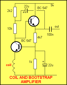
this we have designed 2 circuits:
1. A bootstrap circuit circuit, and
2. A 2-transistor amplifier.

The Bootstrap amplifier shown above has a very high gain
(about 10,000x) and delivers its waveform via the 100n
capacitor.

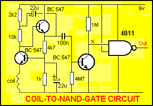
The COIL-TO-NAND GATE circuit shows the three stages
connected together. The circuit will detect very small voltages produced by
the coil and the output of the gate will be a true digital waveform.
The output will sit LOW and change to HIGH when a signal is
detected.
In place of the NAND gate, the output of the transistor stage (line
"X") can be taken to the input of a microprocessor so that the
"counts" from the coil can be monitored. The coil may be counting
metal objects passing on a conveyor belt in a manufacturing process or the
swing of a pendulum etc.
This circuit is not designed to measure intensity or closeness of an object
- it only measures pulses.
On the animation (via the "click" button on the left) you will see
the coil in action when a magnet passes across (or through the centre of the
coil) and both a positive and negative output is produced to
form a COMPLETE CYCLE (a complete wave). This will turn the transistor ON
and OFF. Via the circuit, a square wave (ON
and OFF waveform) will be produced, suitable for injecting into a digital
circuit.
On the next page we will show a circuit for a high-output magnetic pick-up
(one of the technical names for the "coil").
NEXT

|


