|

The
UJT Transistor
The Uni Junction
Transistor

INDEX
Page 56 
This
transistor is rarely used in a hobby-circuit because there are a
number of alternate ways to produce the same effect, however it is interesting
to know how the Uni Junction Transistor works, so you can see why it lost
favour.
The UJT is especially designed to connect to SCR's and this is where its main
application lies.
It only needs 3 or 4 external components and the UJT will produce an oscillator.
The output of the oscillator can be a saw-tooth, if you carefully pick off the
waveform across the capacitor, but more often the output is taken between B1 and
the negative rail. This is where the LOAD is designed to be placed. The waveform here is a spike, and has an amplitude of about
2v for a 6v supply (from 0v to +2v).
The diagram below shows the UJT in a typical arrangement with a low-impedance device,
such as a speaker, between B1 and 0v rail.
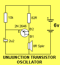
The way the circuit works is this:
The capacitor charges via the 10k resistor During this time the resistance
between B1 and B2 is infinite. The charging is a sawtooth waveform
because the charging is a rising gradient and the discharge is very rapid - into
the speaker. The emitter detects when the voltage rises to 4v
(for a 6v circuit) and at this point the transistor "turns on" and the
resistance between the Emitter and B1 becomes very low and is effectively
equivalent to a diode in forward-bias.
The voltage (the energy) in the capacitor is then passed to the speaker and this
produces a "click." This is the only way the speaker gets its energy. The voltage across the capacitor falls very
rapidly and when it
reaches about 1v (for a 6v circuit), the transistor turns off and the cycle
repeats.
It is important to note that the speaker does not receive any current via the
resistor connected to B2 and this resistor has very little effect (almost
no effect) on the
volume produced by the speaker.
The only way to increase the loudness of the tone is by adding a buffer
transistor.
Doubling the supply voltage will alter the frequency of the output very slightly
and the voltage across the speaker will increase to 10v, but the width of the
spike is so narrow that very little energy is passed to it.
The circuit is reliable in operation. It will work on almost flat batteries (a
high impedance supply) but you have to be careful with the choice of resistors
and capacitors. For instance, if the 10k is reduced to 1k, the circuit will
simply refuse to work with the 2u2 electrolytic so the circuit below may
"freeze-up" if the wrong ratio of R and C is selected. The
"freeze-up" may also depend on supply voltage so, all in all, the circuit
has some limitations that must be overcome by building a prototype before
deciding on the final design.
The
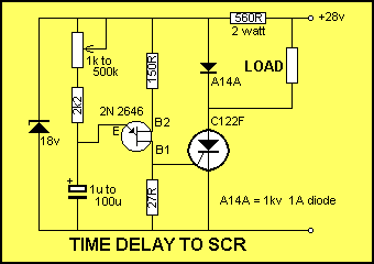
circuit below shows a common use for a UJT - to "fire" an
SCR after a pre-determined period of time.
The LOAD will remain active (the SCR will remain "triggered") and the supply voltage must be removed to
de-energise the LOAD - a bit messy - in the days of microcontroller designs,
this can be done much more conveniently with a chip.
All Talking
Electronics projects are now microcontroller based and
it is only a matter of adding a few extra lines of code to produce almost any
sound you need. UJT transistors are expensive and difficult to obtain, however
the circuit consumes only about 1mA @6v or 2mA at 12v and this may give it an
application where very little is required to be consumed.
Note: many hobby circuits show the UJT drawn incorrectly. B1 must be connected
to the device being activated as the energy from the capacitor flows via the Emitter-B1
circuit to the device. The transistor will not work around the other way,
however it will not be damaged if momentarily connected incorrectly.
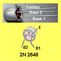
The tab is actually between B2 and E.
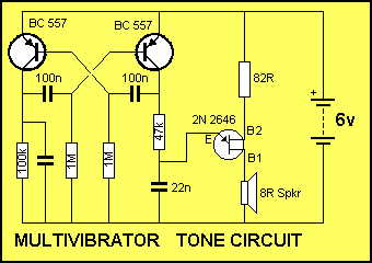
The UJT can be gated "on and off" by controlling the 47k "charging resistor."
The circuit below shows an "up-side-down" multivibrator turning on the
tone circuit (the UJT circuit):
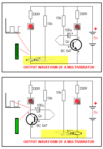
The Basic Electronics Course studies the "standard"
multivibrator as shown below. This standard circuit can be turned
up-side-down if needed. The animation below shows how one side of the
multivibrator turns on then the other side to activate each LED. In the circuit above, the multivibrator takes the
47k to the
positive rail, to activate the tone circuit.
Learn how the circuits above can be created by lines of code in
a PIC microcontroller chip in our PIC Programming Course.
Don't
forget: UJT's are difficult to get and expensive, when compared to transistors
and other standard semiconductors.
NEXT
| 


