|
Creating a
Program

Page 28
INDEX

This page contains more help on creating a program.
The example we have provided comes from the PIC
LAB-1 project and is the first project you should construct to learn about
PIC Programming.
EXPERIMENT 1
Turning on a LED
This experiment
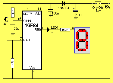
turns on a LED when button A is pressed.
The button is connected to the lowest bit of Port A (bit0). When the button is
pressed, the line goes HIGH. This is called positive logic.
The LED is
connected to the lowest bit of Port B (Bit0). Any bit of any port can be
an input or output. It is convenient to
make port "A" an input and port "B" an output. Port A has
5 lines and port B has 8 lines.
The circuit below shows the active components for Experiment 1. The switch
is connected to RA0 and the LED is connected to RB0.

The circuit for Experiment 1
Any port-line can be changed from an input to an output or vice versa, at any
time, during the
running of a program.
If you are going to change the direction of a port-line, you must take into
account any devices connected to the line. For instance, if a switch is
connected between an output of the chip and rail; if the line is an output and
is made LOW, the chip will be damaged when the button is
pressed.
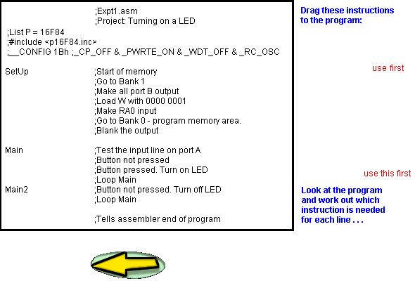
The program consists of two loops in Main. The first instruction in Main looks at the
input line and determines if the button has been pressed. This where a decision
is made. If is is not pressed, the micro is taken to the next
instruction in the program and a loop is executed that makes an output line
LOW to turn off a LED. If it is pressed, the micro is taken to the third
instruction in Main to turn ON an output bit to illuminate a LED.
The micro never stops executing instructions. It must be executing one
loop or the other.
Main must be a loop (or more than one loop) as this is where the LED is
turned ON and OFF and the microcontroller will loop this routine many
times per second.
In Main, instructions will take the micro to other routines called sub-routines, carry
out operations such as delays, produce beeps, etc and return to Main,
as you will see in a moment.
Study the following experiment then go to the interactive "drag"
program below.
You will required to drag the instructions with your mouse, to create the
program.
;Expt1.asm
;Project: Turning on a LED
List P = 16F84
#include <p16F84.inc>
__CONFIG 1Bh ;_CP_OFF & _PWRTE_ON
& _WDT_OFF & _RC_OSC |
SetUp
Main
Main2
|
ORG 0
BSF 03,5
CLRF 06
MOVLW 01
MOVWF 05
BCF 03,5
CLRF 06
BTFSS 05,0
GOTO Main2
BSF 06,0
GOTO Main
BCF 06,0
GOTO Main
END
|
;This is
the start of memory for the program.
;Go to Bank 1
;Make all port B output
;Load W with 0000 0001
;Make RA0 input
;Go to Bank 0 - the program memory area.
;Blank the display
;Test the input line on port A
;Button not pressed
;Button pressed. Turn on LED
;Loop Main
;Button not pressed. Turn off LED
;Loop Main
;Tells assembler end of program
|
|
|
