|
LED |
|
A complete kits of parts and PC board costs $5.00 plus postage from: Talking Electronics. Email HERE for details. |
When replacing tail lights
with "tail-light-assemblies" containing LEDs, the amber turning-indicators will not flash
because the LEDs do not take sufficient current to operate the
"flasher" unit in the cabin.
Here is a typical replacement containing 2 red STOP LEDs and 3 AMBER
TURNING LEDs:

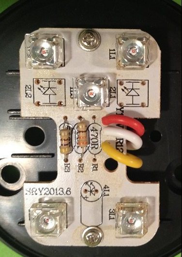
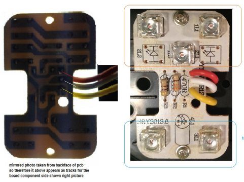
The 3 LEDs on the PC board above
for the "Turning Indicator" are in series.
Normally the yellow and white leads are connected
to the "turning Indicator lead" (from the cabin) and chassis.
But of the flasher unit in the cabin does not "flash,"
you need the Multivibrator circuit below to make the
LEDs flash.
![]()
Connect the yellow and white leads
to the flasher circuit
![]()
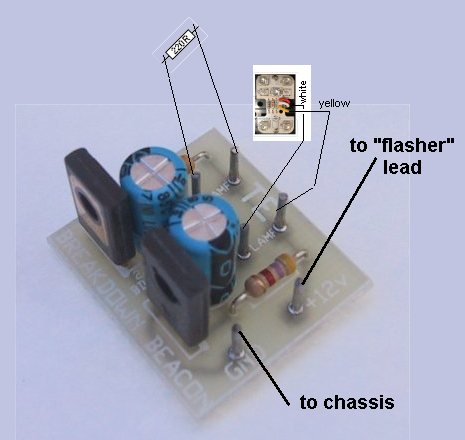
Connect the yellow and white of the tail-light
assembly to the "lamp" holes
on the PC board and connect the +1v to
the "flasher" lead and GND to chassis
The three Turning Indicator LEDs can be placed in series as in the tail-light photos shown above or they can be placed in Parallel as shown in the following circuit:
![]()
When placed in series, the total current
will be less than 30mA and when placed in Parallel, the total current
will be about 90mA.
Both arrangements will produce the same flash-rate but the parallel
connection will allow the LEDs to turn off fully between flashes.
20/7/2014