Links to more pages on Metal Detectors:
http://www.next.gr/sens-detectors/metal-detector-circuits/
The Fundamentals of Electronic Prospecting - a discussion on
different types and their capabilities
http://www.goldgold.com/the-fundamentals-of-electronic-prospecting.html
Geotech: Lots of circuits of well-known metal (gold)
detectors:
http://www.geotech1.com/cgi-bin/pages/common/index.pl?page=metdet&file=schematics.dat
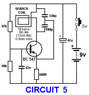
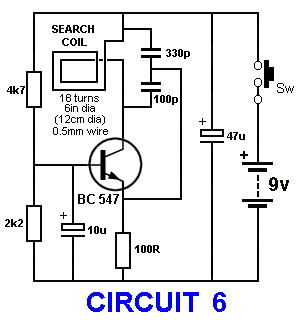
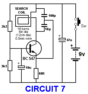
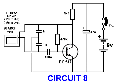
Remember this: almost all circuits (up to about 4 - 6 transistors) have the
same capability: detecting a 20mm coin at about 100mm. It doesn't matter if the
circuit is simple or complex, The sensitivity revolves around the circuit
driving the coil. Some circuits are more sensitive to "interference" and we have
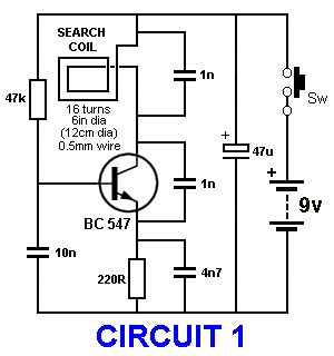
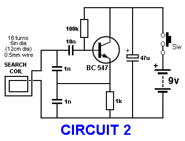
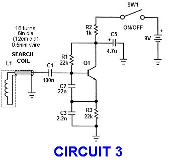
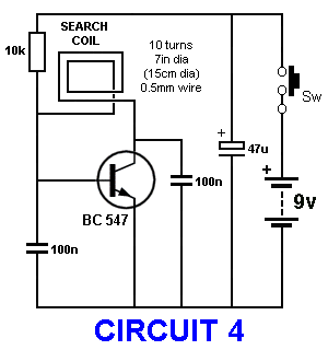
demonstrated this in Circuits 1 - 8 at the end of the page. The
most-sensitive circuit is a 100mm dia coil with just 12 to 20 turns and operates at about
200kHz as shown in circuit 8. The frequency of the circuit will change by one Hertz and this can be
detected on an AM radio. You cannot get better than this.
The simplest circuit is shown below:
Another Simple Metal Detector Circuit
To learn more about the
basics of circuit-design and recognise components, component-values, go to our:
Basics Electronics 1A
We also have two Metal Detector Projects:
Metal Detector MkI
Metal Detector MkII
BASIC CIRCUITRY of
METAL DETECTION
by
Charles D. Rakes
Note by Colin Mitchell:
The first part of this discussion is a very old article using US imperial measurements,
by Charles D. Rakes. A table of
wire gauges is provided at the end of the article. The rest of the
circuits are from different sources.
All these circuits have about the same sensitivity as the single
transistor circuit shown in fig 7 of Part II (shown below), using
an AM radio as the receiver. They have been included to show the
ingenuity of design-engineers, in an attempt to improve the performance.
Here is a reference from another website with exactly the same views as myself:
The Beat-frequency oscillator (BFO)
is the simplest (and oldest) type of metal detector technology and is a good
starting point for learning how metal detectors work. The basic beat-frequency
metal detector employs two radio frequency oscillators which are tuned near the
same frequency. The first is called the search
oscillator and the other is
called the reference oscillator.
When a metallic object disturbs the magnetic field of the search coil, the frequency of the search oscillator shifts slightly and the detector will produce a signal in the audio frequency range.
Although once popular, BFO's are no longer being made by professional metal detector manufacturers. They are simple and inexpensive, but do not offer the accuracy and control of modern PI or VLF detectors. Attempts have been made to add new features such as discrimination and more advanced models were produced in the 1970s, but they were soon replaced by recent, more sophisticated technology.
BFO designs are still used in cheap hand-held devices and in low quality, toy type detectors.
The Simplest Metal Detector Circuit is also shown below and it
only requires 4 components.
Using a Faraday Shield around the search coil will reduce the effect of
the ground altering the frequency if the ground has a large amount of
iron in the rocks. Simply wind aluminium foil around the turns of the
search coil and leave a small gap where the wires exit.
It is pointless going to a lot of work building a complex receiver (as
shown in a number of the circuits below) as the result will be no better
than the simplest circuit.
All these circuits are limited to picking up a coin at 90mm to 150mm.
Basically, a 90mm coil with pick-up to 90mm and 150mm coil will pick-up
to 150mm.
An AM radio will detect the change in frequency of a few cycles at 150Hz
and you cannot get better than that.
To get a deeper penetration, you need to deliver very high energy to the
coil to produce magnetic flux that enters the ground and gets stored in
the gold nugget.
The coil is then turned off and the circuit listens for the collapsing
energy from the gold nugget being released and detected by the coil.
This is called Pulse Injection technique and will be covered in
later circuits.
For now, here are some simple circuits:
Metal Detection Basics
One of mans greatest challenges
throughout history is to see what cannot be seen, to detect what is
hidden, and to reap riches from these treasures. This visit were going
to look at some very basic metal-detection circuits. Now don't get me
wrong; the circuits we'll share here most likely will never locate a
valuable treasure, but they can be put to use performing other more
practical applications. However, in the early days of the last century,
even the simplest of metal detectors were successful in discovering
some very valuable buried treasures. Simplicity often is the best route
to take in solving a seemingly difficult task. Never give up on an
electronic adventure because you don't have the latest and greatest
equipment.
Ferrous Ferrets
Our
first example of a ferrous detector
is a simple mechanical device shown in Fig. 1.
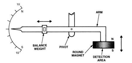
The detector is a modified balanced scale, which indicates ferrous
objects and magnetized items. A magnet is attached to one end of the
arm and a simple north/south scale is attached at the opposite end. A
pivot is located near the magnet end of the arm and a slide balancing
weight is on the opposite end.
The magnetic scale should be balanced with no ferrous items near by. Any
non-magnetized ferrous object positioned below and close to the magnet
will cause the pointer to go up due to the magnetic attraction.
The magnetic scale should be balanced with no ferrous items near by. Any
non-magnetized ferrous object positioned below and close to the magnet
will cause the pointer to go up due to the magnetic attraction.
A magnetized object with the south pole facing up will cause the pointer
to go down, and when the north pole faces up the pointer will rise. This
ultra-simple magnetic detector is very sensitive and will easily
determine what objects are ferrous and the polarity of magnets.
Electronic Ferrous Ferret
Our first electronic metal detector circuit, see Fig. 2, uses a Hall
Effect sensor to detect weak permanent magnetic fields. Almost all
ferrous objects retain some degree of magnetism, and those that do are
easily detected with our Hall Effect ferrous-detector circuit.
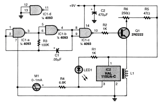
Fig. 2. The electronic version of the Ferrous Ferret uses a
simple Hall Effect IC.
Weak magnetic fields can be detected with this easy-to-build device.
The HAL 115UA-C IC Hall Effect sensor is the heart of the weak-field
detector circuit and is available for less than a buck from Digi-Key.
This Hall Effect sensor is a bipolar device that is sensitive to a
magnet's north pole on its branded side and to the south pole on the
opposite side. The branded side, see Fig. 3, is the side that displays
the part number.
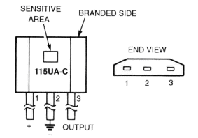
Fig. 3. Let's get up close and personal with our friend—the HAL
I15UA-C.
The branded side-where the part number is displayed—is sensitive to a
magnet's north pole,
while the opposite side is sensitive to a magnet's south pole.
The sensor's output (pin 3) is normally low when no external magnetic
field is present. Placing a magnet with its north pole facing the
branded side of the sensor will cause the output at pin 3 to go high.
Placing a magnet with its south pole facing the non-branded side will
also cause the output to go high.
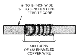
Fig. 4. Utilizing some skill and patience, inductors can be
hand-wound.
Here is a simple diagram showing the typical inductor needed for
metal-detector circuits.
Here's how the circuit operates. Two gates of a 4093 quad, 2-input, NAND
Schmitt trigger IC are connected in a low-frequency square-wave
oscillator circuit operating at about 100 Hz. The output of gate "C"
drives the base of Q1, which is connected in an emitter-follower circuit
supplying the 100-Hz signal to L1. Inductor L1's drive level is set by
R6. The output (pin 3) of IC2 is connected to an LED and a metering
circuit.
Inductor L1 supplies a low-frequency AC bias to the backside of the Hall
Effect sensor, IC2. This AC bias in effect increases the Hall Effect
sensitivity many times over and also allows it to detect both north and
south pole magnets from the branded side; however, the circuit is much
more sensitive to north pole fields. The arrangement of L1 and the Hall
Effect sensor is shown in Fig. 5.
Fig. 5. The Hall Effect IC works in conjunction with the
inductor.
A low-frequency AC bias is supplied to the backside of the IC via the
inductor.
The Hall Effects output waveforms are shown in Fig. 6. The waveforms are
observed at pin 3 of the Hall Effect IC. Output waveform "A" is set by
adjusting R6 for a symmetrical output without any ferrous metals in the
pick-up area. If a scope is not handy, a DC voltmeter can be used to set
the output to about 4.5 volts. This setting will produce an output
waveform very close to the one shown in Fig. 6A. The "B" output waveform
occurs when the north pole of a magnet is brought in proximity of the
Hall Effect sensor. The south pole of a magnet produces the output
waveform shown in Fig. 6C.
Fig. 6. Here are the waveforms that might come from pin 3 of IC2.
Resistor R6 can be adjusted to calibrate the circuit.
Winding L1
Inductor L1 (see Fig. 4) is fabricated by jumble winding 500 turns of
#32 enamel-covered copper wire on a
¼-inch diameter ferrite rod. The rod's actual diameter and length are
not critical, and any size rod material from ¼inch to ½inch in diameter
will do. The rod's length can be anything from 1 inch to 3 inches. The
type of rod material suitable for this application can be salvaged from
an old AM transistor radio or some older TVs.
If the rod material cannot he located, don't give up 'cause there are
other paths to take. A relay coil with a resistance of 10 ohms or
greater will generally work for L1. Some miniature audio transformers
have straight sections of laminations that can be used in place of the
rod material. Most of the rod material I've used and have recommended
here is actually designed for much higher frequency use. As a last ditch
effort, try a number of small nails taped together as a core for L1 and
see what happens. Here's a great place to experiment with various coil
core materials and windings to improve or vary the circuit performance.
Keep me informed on your efforts.
Try This One
Something else came to mind after disassembling the circuit, and due to
time restraints I was never able to check it out. I would like to
challenge you to do so. What if a second Hall Effect IC sensor was added
to the circuit but placed beside IC2 with its branded side facing L1's
core?
Fig. 5. The Hall Effect IC works in conjunction with the inductor. A
low-frequency AC bias is supplied to the backside of the IC via the
inductor.
Duplicate IC2's circuitry with the new IC, but leave out the metering
circuit. See Fig. 7 for details. Try to get like waveforms from both
circuits by adjusting R6 and positioning the two ICs on the end of L1.
Connect one lead of a digital DC voltmeter to pin 3 of IC2 and the other
meter lead to pin 3 of the added IC. If I'm correct, the circuit should
be as sensitive to the south pole of a magnet as the original circuit
was to the north pole. If not, try connecting a DC voltmeter to the
output of IC2 and another voltmeter to the output of the added IC. IC2
should remain more sensitive to the south pole of a magnet, and the
added IC should be more sensitive to the north pole.
All Metals Detector Circuit
Our next metal detector circuit takes us back into the early years of
the last century where tubes were king and semiconductors were only
diodes. It was discovered early on that any metal object placed near the
tank circuit of an oscillator would shift its frequency either up or
down. A tank circuit is the combination of an inductor and capacitor
that make up a tuned circuit. Ferrous metals near the inductor of a
tuned circuit cause the oscillator's frequency to go down and
non-ferrous metals cause the frequency to increase. This is the basic
effect that the Beat Frequency Oscillator (BFO) type of metal detector
uses to detect all metals. Figure 8 shows a block diagram of the
circuits making up a typical BFO detector. A search loop is usually
wound in a circular fashion to serve as the inductor in the search
oscillator's tank circuit. The reference oscillator is very similar to
the search oscillator with a much smaller inductor, which is usually
shielded from the search loop. RF signals are taken from both
oscillators and fed to a common mixer, where the sum and difference
frequencies of the two oscillators are mixed. The sum frequencies are
filtered out, leaving only the audible difference frequencies to pass on
to the amplifier and headphones.
Fig. 7. Increase your odds at detection with this simple modification.
An additional Hall Effect IC is added to balance the circuit's
sensitivity to the north and south magnetic poles.
Fig. 7. Increase your odds at detection with this simple
modification.
An additional Hall Effect IC is added to balance the circuit's
sensitivity to the north and south magnetic poles.
As a practical example, we'll set the search oscillator up to operate at
a frequency of 100,100 Hz, and the reference oscillator to a frequency
of 100,000 Hz. The difference frequency between the two oscillators is
an audible 100 Hz that is fed to the headphones. The search coil is then
moved over a small ferrous metal object causing the oscillator to drop
in frequency to about 100,050 Hz. The audible 100 Hz tone drops to 50 Hz
indicating a metal object is located somewhere near the search loop. A
non-ferrous object near the loop will cause the oscillator to increase
in frequency and produce a higher audio output tone. A carefully
adjusted BFO metal detector can be used to discriminate between ferrous
and non-ferrous metals.
Fig. 8. The popular loop-detector circuit has been a mainstay for
many treasure hunters.
A set of headphones allows the user to hear an indication of ferrous
material and magnetic fields.
Two-Transistor BFO Detector
One of the simplest BFO metal locators to build is the two-transistor
circuit shown in Fig. 9.
Fig. 9. This is the schematic for a Beat Frequency Oscillator
metal-detector.
Two transistors are used as the oscillators in this circuit.
The circuit may be set up to operate on any frequency between 50,000 Hz
to over 1 MHz by selecting the tank circuit components. Just about any
good general-purpose NPN transistor suitable for low RF applications
will work just fine. The search loop can be as small as a dime or three
feet or larger in diameter. A small loop works best for small objects
buried shallow and a large loop works best for large objects buried at
greater depths. The two oscillator circuits should be separated and
shielded from each other to reduce frequency pulling between the two. A
really well constructed BFO detector will be able to operate with a
difference of less than 100 Hz between the two oscillators. The lower
the audio output tone the easier it is for the ear to tell a small
frequency shift. The detector's maximum sensitivity is obtained when the
two oscillators are operating just a few cycles apart. Believe me, this
is not an easy task to accomplish, but one well worth the effort.
Here's how the simple BFO detector operates. Transistor Q1 along with
its associated components make up a Colpitts oscillator circuit with the
search loop, C1 and C3 forming its tuned circuit. Transistor Q2 with its
associated components make up another Colpitts oscillator circuit with
L2, C2, and C4. forming the tuned circuit. The emitters of Ql and Q2 are
coupled together through R1, R2, and the low-impedance headphones. This
circuit arrangement functions as a simple RF mixer circuit. The audio
frequencies are fed to the headphones, and the RF frequencies are
bypassed to ground through C8.
Winding And Scrounging
The loop may be wound on almost any round insulated non-metallic form,
such as wood or plastic. Inductor L2 can be an old ferrite rod antenna
coil removed from an AM transistor radio, or one can be made by winding
a coil on a round insulated form. Let me offer the following winding
suggestion to get you going on building the BFO circuit. Locate a 10- to
12-inch wood or plastic hoop that's about 3/4-inches wide and close wind
ten turns of #18 to #22 enamel-covered copper wire evenly around the
forms. Tape over the wire with plastic electrical tape and connect to
the circuit with a length of two-wire zip cord. If an antenna coil
cannot be found for L2, then close wind about 80 turns of #22
enamel-covered copper wire on a 1-inch plastic pill bottle or plastic
pipe.
One important thing to do in selecting the two inductors is to be sure
that the reference oscillator can tune to the same frequency as the
search oscillator. If a frequency counter is available then the chore
will be super easy. If not, some experimenting with different pairs of
capacitors (C1 and C3 or C2 and C4) will be necessary to bring both
oscillators to the same frequency.
Part II
Single Transistor Circuit
Before getting into the circuitry, we had better take a quick look at
how the single-transistor detector system operates. I'm sure that at
some time you've heard a whistle or tone while tuning your AM broadcast
receiver or, even more likely, when listening to an AM short-wave
broadcast station. In radio circles, this is referred to as a heterodyne
signal. An AM receiver detecting two RF signals, which are very close in
frequency, usually causes this condition. If the two RF frequencies are
less than a few kHz apart, an audio tone (difference frequency) will be
heard. This is basically how our single-transistor detector circuit
operates.
In our single-transistor circuit, see Fig. 1, only one RF oscillator
circuit is used. The other RF signal is supplied by one of many AM
broadcast radio stations. A portable transistor AM radio receives the
two RF signals and outputs an audible tone. The mixing and audio
amplification is handled by the transistor radio. If either RF signal
shifts in frequency, the audio tone will increase or decrease by the
same amount. Since the frequency stability of all licensed AM broadcast
stations is rock solid, only our search oscillator will produce a shift
in frequency. The end result is a detector that operates like our
two-transistor circuit, but requires less parts and time to construct.
The oscillator circuit in Fig. 1 is very similar to the oscillators used
in our previous circuit. Transistor Q1 is connected in a Colpitts
oscillator circuit with components C2, C3, C5, C6, and LI making up the
oscillator's tuned circuit. Changing any one or any combination of these
components will vary the oscillator's operating frequency.
Increasing the value of any capacitor will lower the oscillator's
frequency and decreasing the value will increase the frequency.
Increasing L1's inductance will also cause a decrease in frequency and
vice versa.
Fig. 1. Here is the schematic for the single-transistor circuit.
Transistor Q1 is a general-purpose, NPN transistor; and it serves as the
heart of a Colpitts oscillator circuit.
PARTS LIST FOR THE SINGLE-TRANSISTOR CIRCUIT (FIG. 1)
SEMICONDUCTORS
Q1—2N3904, or similar general-purpose NPN transistor
RESISTORS
(All resistors are ¼-watt, 5% units.)
R1—1000-ohm
R2—270,000-ohm
CAPACITORS
C1—.01-uF, ceramic disc
C2—.0001-uF, ceramic disc
C3—-.005-nF, ceramic disc
C4—.1-uF, ceramic disc
C5 4 to 34 pF, 7-mm, ultra-miniature trimmer, Mouser part
#24AA113
C6— 12-100 pF, Mouser part #242-3410-70
ADDITIONAL PARTS AND MATERIALS
S1—SPST switch
L1—Loop, see text
The 6 turns of copper wire can be wound on a rigid material, such as
wood or plastic.
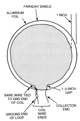
Fig. 3. This detailed diagram of the loop shows the leads
extending from the copper wire, as well as the makeshift Faraday shield.
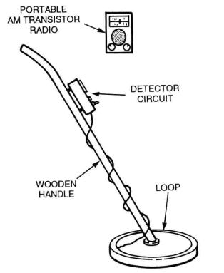
Fig. 4. Here is an artist's diagram of the completed
metal-detector unit.
Any inexpensive AM transistor radio can be used in conjunction with the
detector.
Building The Loop
The search loop may be constructed in several different ways; however,
the method offered here should get you headed in the right direction.
Refer to Fig. 2 as a guide for constructing the loop. The loop form
should be constructed from non-metallic and non-moisture-absorbent
material. A sealed wood form will do, and it can be either solid or
hoop-like. The form should be % to 1 inch wide to allow room for the
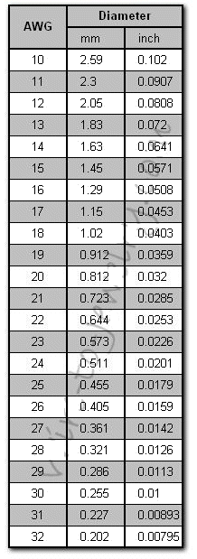
coil windings. Close wind six turns of #20 enameled or insulated wire on
the form. Wrap the windings with at least two layers of good quality
plastic electrical tape. Put the loop aside and construct the oscillator
circuit on a piece of multipurpose PC board with pre-drilled holes.
Stability is one of the most important considerations in building any
stable oscillator circuit, so keep all component leads short and solidly
mounted.
The two variable capacitors should be mounted in a manner that allows
tuning from outside the enclosure. In order to achieve the best results,
the circuit should be housed in a metal cabinet to which the circuit
ground is connected. Temporarily connect the loop to the circuitry with
about 30 inches of shielded microphone cable or 2-conductor intercom
wire. Any wire gauge from #18 to #24 will do. Actually two insulated
wires may be twisted together by hand and used.
Place the loop away from any metal object and apply power to the
circuit. Locate a transistor radio near by and tune in a station
somewhere near the middle of the dial. Adjust both C5 and C6 to a
frequency that will heterodyne with the broadcast station. If nothing
happens, it is most likely that the oscillator is not operating near the
desired frequency. Now, how do we determine if the oscillator's
frequency is too low or too high? Naturally, a frequency counter would
be the easiest way to determine the oscillator's frequency. If one is
not available, what then? A shortwave receiver that runes both below and
above the standard AM broadcast band can be used to ferret out the
oscillator's frequency.
Once the oscillator's frequency is determined, adjustments can be made
to move the frequency into the broadcast band. Reducing the total
capacitance of the oscillator's tuned circuit or lowering the inductance
of the loop will raise the frequency. Lowering the frequency is
accomplished by increasing the capacitance of the tuned circuit or by
increasing the inductance of the loop. Removing or adding a turn to the
loop is a good method to use if the oscillator is way off frequency.
Adding A Faraday Shield
The search loop normally scans the ground in a parallel manner in search
of metal objects. The loop's parallel position to the ground forms a
capacitance to ground, which shifts the oscillator's frequency. As the
loop moves up and down above the ground, the oscillator's frequency
shifts in a like manner. Adding a Faraday shield to the loop will help
in reducing the ground-effect frequency-shift problem.
The Faraday shield is a metal shroud that is formed around the loop with
an insulating gap in the middle. A shield can be formed out of aluminum
foil by cutting a length that's 3 inches wide and long enough to go
almost completely around the edge of the loop while leaving a gap of 1
to 2 inches in the middle, see Fig. 3. Once the aluminum foil is formed,
add a 4-inch length bare wire under the foil at one end and glue the
shield in place. Place the loop on a flat surface and place a solid
object on top to secure the foil to the loop form. After the glue dries,
connect the other end of the bare wire to the loop's ground-end
connection.
An old broom handle or dowel rod is attached to the middle of the loop
and serves as the handle and support for the loop and detector circuit.
See Fig. 4. The AM radio may be attached to the handle as well or
carried separately.
Position the loop over the area to be searched and tune the oscillator
to produce an audible beat frequency tone. Maximum sensitivity is
achieved when the oscillator is within a few cycles of the broadcast
station. This detector will detect all types of metal, so be ready to
dig, and then dig some more.
Fig. 5. The crystal-filter metal-detector circuit is shown above.
The narrow band-pass of the crystal allows for a high sensitivity to
minute frequency changes.
PARTS LIST FOR THE CRYSTAL-FILTER DETECTOR (FIG. 5)
SEMICONDUCTORS
D1, D2—1N9L4 silicon signal diode
Ql, Q2—2N3904, or similar general-purpose NPN transistor
RESISTORS
(All resistors are ¼ watt, 5% units.)
R1,R3— 1000-ohm
R2—270,000-ohm
R4—-See text.
CAPACITORS
C1—.01uF ceramic disc
C2—,0001uF ceramic disc
C3—.005uF ceramic disc
C4— 0.1uF ceramic disc
C5—See Parts List for Fig. 1
C6—See Parts List for Fig. 1
ADDITIONAL PARTS AND MATERIALS
XTL1—1-MHz crystal
Ml—50-uA to 1-mA meter
Metal cabinet, PC board material, etc.
Crystal-Filter Detector
Our next entry is a version of one of my favorite metal-detector
circuits. A loop and an oscillator circuit similar to the one in our
previous detector are the basic ingredients used in the crystal-filter
detector. The addition of an emitter follower gives isolation to the
oscillator and supplies a low-impedance source for the crystal. The
output is rectified by D1 and D2 and fed to the meter. Take a look at
Fig. 5, as you continue to read the circuit description.
Here's a brief description of how the crystal-filter metal-detector
circuit operates. The oscillator is tuned to the series resonance
frequency of the crystal, which can be any frequency from 100kHz to over
1MHz. However, in our circuit, a 1-MHz crystal is used. When the
oscillator is operating at the crystal's frequency, the output at the
meter is at maximum.
Any shift in the oscillator's frequency will cause a reduction in the
meter reading. The circuit is very sensitive to small frequency shifts
due to the crystal's narrow band-pass characteristics in the series
mode. The basic loop construction used in the previous detector circuit
may be used here as well.
This detector's circuitry should be constructed in the same manner as
our previous circuit. If any component moves or vibrates during use, the
meter will falsely indicate a detected object. Build it solid. The
choice of the meter used for M1 can vary from a sensitive 50-uA to a 1mA
movement. The value of R4 is selected for a full-scale meter reading
when the oscillator is operating at the series-resonance frequency of
the crystal.
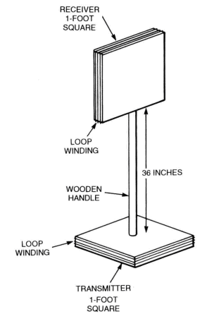
Fig. 6. The detector shown in the above diagram is excellent for
deep level searches.
The "90-degree out-of-phase" relationship of the two square loops helps
limit cross-interference between the transmitter and receiver, thus
eliminating feedback during operation.
Transmitter/Receiver Detector
Our last detector circuit is suitable for locating large metal objects
at greater depths—feet instead of inches. This two-box detector has been
around for about 75 years and is still one of the most popular
deep-searching detectors. The basic system is shown in Fig. 6.
Two non-metallic boxes serve as the 2 housing for the electronics and
the forms for the loops. The transmitter and receiver boxes are mounted
on a 3-foot-long wood handle, with the receiver placed in a horizontal
position and the transmitter in a vertical position. This 90-degree
relationship between the transmitter and receiver allows for minimum
transfer of signal between the two loops. Placing a large metal object
between the two loops causes the transmitter's field to distort,
allowing some of the signal to reach the receiver's loop. The signal is
amplified by the receiver and indicated on the meter as metal detected.
Building The Transmitter
We'll start with the transmitter circuit first, (see Fig. 7) because it
is the simpler of the two units. The transmitter circuit is very similar
to our previous two oscillator circuits, with a slight variation in the
base bypass circuit. The values of frequency-determined capacitors, C1
and C2, are the same. Depending on the size of the loop, they can vary
from .01 to .1-LlF.
The receiver loop normally requires a capacitor equal to Vi the value of
C1 or C2 in the transmitter circuit. The transmitter loop is tuned with
C1 and C2, which are always the same value. The actual value of
capacitance across the transmitter loop is Vi the value of either C1 or
C2. It is most important that both loops are tuned to the same
frequency.
About any loop size from 8 to 12 square inches will do, but we'll stick
to the 12-inch box and offer values for that size. The loops are formed
by close winding 20 turns of #24 to #26 wire around each housing. Run
about 8 inches of wire from each end of the loop to the inside of the
housing for circuit connections. Tape the winding in place with plastic
electrical tape.
The operating frequency will be somewhere between 35 kHz and 50 kHz. The
capacitor values for C1 and C2 are 0.1uF for the transmitter and .05-uF
for C1 in the receiver circuit. Less turns or smaller loops may be used
for higher frequency operation. Try and keep the operating frequency
below 200 kHz, as this type of metal locator works best at low
frequencies.
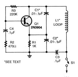
Fig. 7. The transmitter circuit in the above schematic operates
in a range of 35 to 50 kHz.
The oscillator circuit is similar to the previous two mentioned.
PARTS LIST FOR THE TRANSMITTER (FIG. 7)
SEMICONDUCTORS
Q1—2N3904. or similar general-purpose NPN transistor
CAPACITORS
C1.C2— .01 to 0.1uF, ceramic disc (see text)
C3, C4— 0.1-u.F, ceramic disc
RESISTORS
(All resistors are ¼watt, 5%)
R1—1000-ohm
R2—270,000-ohm
R3—220.000-ohm
ADDITIONAL PARTS AND MATERIALS
S1—SPST switch
L1—Loop, see text
Building The Receiver
The receiver (see Fig. 8) is a simple two-transistor RF amplifier
circuit with an isolated emitter follower input. The RF signal is picked
up by the loop and coupled through Q1 to the input of the first RF
amplifier stage, Q2. Transistor Q2's RF gain is set by R10. The signal
from Q2's collector is fed to the base of Q3, and Q3's output is coupled
to a two-diode detector circuit. The DC output is indicated by Ml.
The receiver circuitry will fit on a 2 x 3-inch piece of multipurpose PC
board material. Mount the components close to the board with short leads
and keep the input components away from the output circuitry. The meter
can be any DC type with sensitivity of 50-uA to 1-mA. If a 50uA meter is
used, R11 may need to be increased to a 10K potentiometer. Mount the
circuit in the receiver box and connect the loop.
Mount the transmitter box on one end of the wood handle and the receiver
on the other. The receiver will need to be mounted so that it can be
tilted up and down to obtain a balance between the two loops. This can
be accomplished by using a small hinge attached to the end of the handle
and the receiver housing. Once the balance point is found, the receiver
can be mounted in that position.
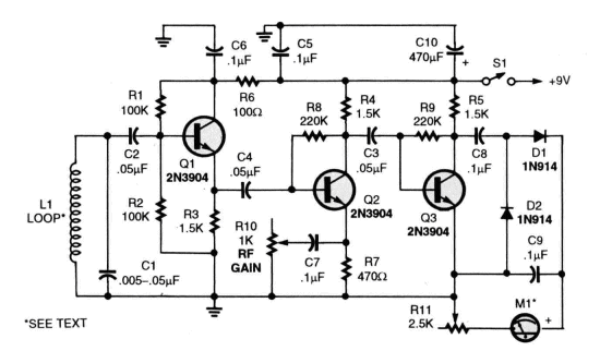
Fig. 8. The receiver circuit.
PARTS LIST FOR THE RECEIVER (FIG. 8)
SEMICONDUCTORS
Q1-Q3—2N3904, or similar general-purpose NPN transistor
D1, D2—1N914 silicon signal diode
CAPACITORS
C1—.005 to .05-uF ceramic disc (see text)
C2 0.1—.05-uF ceramic disc
C5-C9 — 0.1 uF ceramic disc
C10— 470uF 25WVDC electrolytic
RESISTORS
(All resistors are ¼watt, 5%)
R1,R2— 100,000-ohm
R3-R5—1500-ohm
R6— 100-ohm
R7—470-ohm
R8, R9—220,000-ohm
R10— 1000-ohm potentiometer
R11—2500-ohm potentiometer
ADDITIONAL PARTS AND MATERIALS
S1—SPST switch
M1—50-uA to 1-mA DC meter
L1—Loop, see text
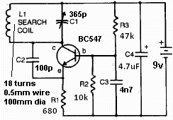
Simplest Metal Detector Circuit
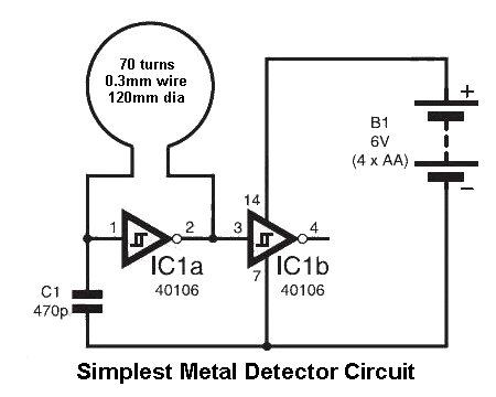
The simplest metal detector circuit consists of 4
components.
The detection-coil consists of 70 turns of 0.3mm wire 120mm diameter.
Place an AM radio near the search-coil and tune it to pick up a squeal.
When a coin is placed near the coil, the tone will alter.
The circuit operates at about 250kHz and the the radio picks up a
harmonic. It will detect a bottle-top at about 90mm.
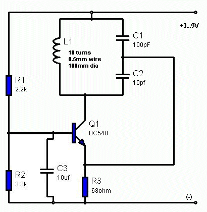
Another simple Metal Detector Circuit consists of two coils that overlap
to provide feedback:
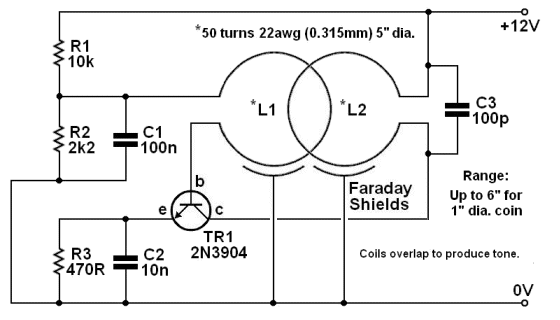
Place an AM radio near the coils and a tone will be heard.
Simple BFO Metal Detector
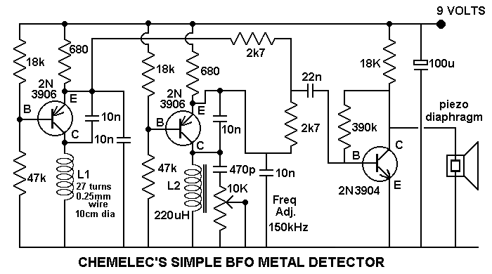
The first two transistors are deigned to produce the exact same
frequency. The result is fed to the third transistor to produce a
beep-beep-beep in the piezo speaker.
When a metal object is detected by L1, (the search coil) the beeping
increases.
The performance of this circuit is no better than the single transistor
circuit above and an AM radio. When it is all boiled-down, the first
transistor drives the coil and the frequency of the circuit changes when
the inductance of the coil is altered by a metal object near it.
The second and third transistors are equivalent to an AM radio by
detecting the frequency of the oscillator and producing a result that is
the difference between the frequency produced by the first transistor
and the frequency produced by the second transistor.
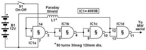
The next circuit is even more complex.
It uses integrated circuits (IC's) to detect the difference between the
two frequencies.
The circuit is very old. All the IC's can now be replaced by an 8-pin
microcontroller and the circuit will be much simpler.
Don't forget, it is no better than a single transistor and an AM radio
and is not worth constructing, however the text is interesting . . .
Simple, sensitive metal detector
Phil Wait
The metal detecting hobby is enjoying quite a boom at the moment and
treasure hunters are not just after gold. The price of the precious
metal has risen in recent months, at around $1,600 an ounce it's worth
going after. Old coins and relics fetch high prices too, so there's lots
to find out there...
METAL DETECTORS depend on detecting one of several effects that can be
observed when a metal object influences the magnetic field surrounding a
coil of wire carrying an alternating current. The principal effects are:
the pattern of the magnetic field surrounding the coil will be altered
and the inductance of the coil will change.
The various types of metal detector devised exploit these changes,
electronically detecting the alteration induced in the coil by the
metallic object. Non-metallic objects or material can also affect the
coil in similar ways.
There are three basic methods employed to exploit the above effects.
"Induction Balance" (IB) metal detectors employ two coils. One is driven
by a modulated oscillator. The other is connected to a detector and
amplifier. The two coils are carefully positioned with respect to one
another such that the receiver coil picks up very little of the energy
radiated by the transmitter coil when no metal or mineral material is
nearby. When the coils are brought near a metal object, the field
pattern is distorted, greatly increasing the transmitted energy picked
up by the receiver coil. The modulated signal is detected and can be
indicated by amplifying the recovered modulation to speaker level as
well as indicating it on a meter. For obvious reasons, this type of
metal detector is often referred to as a "transmit-receive" or TR
detector, sometimes as an IB/TR detector. Chief advantages are good
pinpointing ability and good depth penetration, and they are not
sensitive to small ferrous objects.
Sensitivity suffers badly in mineralised or ironstone ground.
Most IB detectors operate at a frequency between 85 kHz and 150 kHz. As
they are badly affected by mineralised ground a technique was developed
using very low frequency to energise the transmit coil. The 'VLF' types
operate at frequencies around 4-6 kHz, a frequency range which
penetrates all types of soil quite well. However, they need to run at a
fairly high power to achieve sufficient sensitivity with small objects,
hence battery drain is quite high, and pinpointing ability is poor.
"Pulse Induction" detectors employ coils in the search head that are set
up in much the same manner as the IB detector. However, the transmitter
is pulsed so that high energy bursts are transmitted by the search coil.
The receiver then
compares the phase of portion of the received pulse with the transmit
signal. When a ferrous or magnetic object is brought near the search
coils the phase of the received signal is advanced with respect to the
transmit signal. The opposite occurs when a non-magnetic conductor is
brought near the search coils. Thus, this type of detector can
effectively 'discriminate' between ferrous and non-ferrous metals as
well as exclude ground effects — simply by setting the detection
circuitry to exclude signals of the unwanted phase characteristics.
Thus, a "Ground Exclusion" control is often featured with these
detectors. As the strength of the received signal also varies, depending
on the 'target' object's characteristics, this effect may also be
included in the detection process.
Clearly, an IP detector presents many problems to the home constructor.
The simplest technique detects the change in inductance of a single
search coil. If this coil is part of the tuned circuit of an oscillator,
then comparing the frequency of the 'search' oscillator with a stable
reference oscillator will indicate the presence of a metal object. This
detector is called the "Beat Frequency Oscillator" or BFO type. The two
oscillators are set such that there is a slight difference in their
frequencies and their outputs mixed. The resultant will be a 'beat'
frequency which is equal to the difference between the two oscillator
frequencies. The main advantages of this type are simple circuitry and
setting up along with good pinpointing ability. In the past, most
published designs have suffered from a distinct lack of sensitivity as
well as poor tuning stability. A cunning mixing technique and a few
other fillips can overcome these problems.
Hence, our new metal detector is a BFO type incorporating some modern
refinements. It has proved to have similar sensitivity to our IB
detector, the ETI-549, but is generally easier to build and set up,
there being no critical adjustments.
Design features
Our new metal detector has three controls: COARSE frequency adjust, FINE
frequency adjust and VOLUME on/off The coarse frequency control is used
to initially set the frequency of the search oscillator, compensating
for the various factors affecting any drift in this oscillator (mainly
temperature and battery voltage). The fine frequency control is then
used to set the note to a low pitch when the detector is placed over the
ground, permitting compensation for the effect of the ground on the
frequency of the search oscillator. The volume control adjusts the
loudness of the output from the speaker.
The two main design problems this type of detector presents are the
frequency stability of the two oscillators and the minute frequency
change which has to be detected.
The search oscillator we finally used was settled on after some
experimentation. Our first try employed an LC oscillator built around a
CMOS gate chip. This proved to be not as stable as we required and we
found that trying to obtain dc control of the frequency by varying the
supply rail voltage had drawbacks. After some experimentation with
oscillator configurations we hit on a discrete component oscillator
which we found behaved much as we were seeking.
The search coil in the circuit we used is the inductor in a Colpitts
oscillator. However, this particular circuit may be a little unfamiliar
to many readers. To increase the RF current in the coil, it is placed in
the collector circuit of Q1. Feedback is between collector and emitter
and the base is effectively at RF ground. The frequency determining
capacitance of the tuned circuit is 'tapped' to provide feedback, C2 and
C3 performing this function. Careful attention has been paid to the
basic frequency stability of this oscillator. Good quality styroseal
capacitors have been used for C2 and C3. These have a temperature
coefficient roughly opposite to that of other temperature influences on
the frequency of the oscillator. In general, the short-term stability of
this oscillator is quite good.
The particular circuit configuration of the oscillator gave us a very
useful bonus — dc control of the oscillator frequency over a small range. Varying the base bias on a transistor will
vary the collector-base capacitance. In this circuit, the c-b
capacitance is part of the overall 'stray' capacitance that determines
the exact frequency of oscillation. As the base bias is increased the
c-b capacitance decreases, increasing the oscillator frequency. In this
way, the oscillator frequency can be varied over a range of about ten
percent. We have provided two controls, the FINE control providing a
variation of about one-tenth that of the COARSE control.
The search oscillator is loosely coupled via a 47p capacitor to a
following CMOS Schmitt trigger and two inverters which square the
output. The loose coupling isolates the oscillator from the subsequent
circuitry, further enhancing die stability of the search oscillator.
For the reference oscillator, we chose to use a crystal, because of its
inherent stability. It has been argued that if an ordinary LC circuit is
used for the reference oscillator it will have similar drift
characteristics as the search oscillator and the overall drift will be
reduced. In fact, the reference oscillator can be made using a standard
455 kHz IF transformer. In practice however the two tend to drift at
markedly different rates. We think the best approach is to make both
oscillators as stable as possible. Hence the crystal — which is an
easily available type and cheaper than an IF transformer!
The reference oscillator is a simple 'inverter' crystal oscillator built
around one gate from a CMOS quad NAND gate, IC2. This has a square wave
output and drives a divide-by-four circuit, IC3, via the other three
gates in IC2, acting as buffers.
The crystal we used is a 3.579545 MHz type (NTSC chrominance sub-carrier
frequency) commonly available from a number of suppliers. The output
of IC3 is at a frequency of about 890 kHz. The exact frequency is
unimportant, just so long as its stable.
The search oscillator operates at a little above 100 kHz, about
one-eighth of this frequency.
The secret of our metal detector's overall sensitivity lies in the mixer
circuit. This employs one section of a 4013 flip-flop. The reference
oscillator's divider output (at 890 kHz) is applied to the D input of
IC4a and the squared-up search oscillator's output is applied to the
clock input. If the clock frequency (i.e the search oscillator
frequency) changes by 1 Hz, the output beat (from the Q output of IC4a)
will change by 8 Hz (see 'How it Works'), thus considerably multiplying
the smallest changes in oscillator frequency.
The output of the mixer is fed to a simple audio amplifier driving a
loud-speaker. The search and reference oscillators must be well
decoupled from each other and buffered from the mixer stage to prevent
'pulling' of the oscillators, which would result in erratic operation,
especially when set for a low frequency output. We have used supply line
decoupling as well as buffer stages after each oscillator. We also found
it necessary to use a separate battery for the audio stage to prevent
the very short, but high current pulses to the audio stage affecting the
oscillators.
The search coil
The most important characteristic of the search coil is its size.
Surprisingly enough the actual inductance doesn't seem to have much
effect on sensitivity. The greater the coil diameter the greater the
penetration depth, but the less sensitive it is to small objects. As a
general rule the penetration is about equal to the search coil diameter,
while the sensitivity is roughly proportional to the cube of the object
diameter (as expressed as a function of the search coil diameter).
Sensitivity is also inversely proportional to the sixth power of the
distance between the coil and the object.
All this means is that if the object size is halved the sensitivity is
reduced to one-eighth. Also, if the depth is doubled the sensitivity is
reduced to one sixty-fourth. Its easy to see why all metal detectors
which are designed to pick up small objects use small coils, (150 to 300
mm diameter) and really only skim the soil surface. If the search coil
is doubled in diameter for greater penetration the sensitivity to small
objects falls to one-eighth. You rapidly encounter the law of
diminishing returns.
Some of the more expensive metal detectors improve the penetration,
while retaining sensitivity, by using a very complex arrangement of
coils which modifies the field pattern. This can be done to some extent
by making the coil on the BFO detector oval in shape.
We chose a round coil of 150 mm diameter to give good sensitivity to
small objects giving about 100-150 mm penetration which is easy to
build, but this is open to considerable experimentation. Remember
though, that if the coil diameter is increased the number of turns will
have to be reduced so that the search oscillator remains at the same
frequency (about 110 kHz).
Faraday shield
If the search coil is moved around, the capacitance between it and the
ground or other objects changes. This changing capacitance 'pulls' the
oscillator frequency and can completely swamp out the small change in
inductance we are looking for. The coil can be screened from this
capacitance effect by using a Faraday Shield around the coil. This
consists of a ring of tubing, or in our case — a wrapping of aluminium
foil, around the coil but broken at one point so it does not make a
shorted turn. This shield is then connected to the common supply rail
(0V) on the oscillator.
Construction
We have deliberately chosen commonly available mechanical and electronic
components so that construction of this project is as easy as possible —
especially for the newcomer. The search coil is mounted on a 165 mm
diameter plastic pot stand which may be purchased at hardware stores and
nurseries. The electronics are
mounted inside a simple aluminium box attached to a stem made from a
length of tube which extends down to the search coil and serves as the
handle. Connection to shield the search coil is via a length of shielded
cable. The controls mount on one side of the box housing the
electronics. Which side you mount them depends on whether you are right
or left handed. The speaker mounts on the end of the box facing the
operator. As can be seen from the picture, the handle was made with an
upwards bend at the end which you grip. This balances the instrument
reasonably well, avoiding arm strain.
Construction should commence with the electronics. Mount the components
on the pc board, taking care with the orientation of the transistor (Q1)
and the ICs. Do not substitute another type of capacitor for the
styroseal types specified for C2 and C3 or performance may suffer. The
crystal specified comes with flying leads and may be soldered in place.
Don't use too much heat though, solder quickly and you will avoid
possible damage to the crystal.
The next step is to make the stem. The easiest way is to take a length
of 25mm diameter electrical conduit about 850 mm long and make a bend about
100 mm from one end for the grip. To do this, heat the point of the bend
over a flame (not in the flame) until it softens and then carefully bend
it about 60° from straight.
A length of aluminium tube may also be used for the handle. The bend for
the grip can be made by first flattening the point of the bend somewhat
with a hammer then placing the short piece in a vice and carefully
making the bend. A section of wood dowel or plastic tube should be
placed between the search coil and the end of the metal tube to keep the
mass of metal about 200 - 250 mm away from the search coil. A piece of
wood dowel of the right size, jammed in the end of the aluminium tube,
is generally the easiest way to go about it.
We used a small aluminium box which comes in two pieces. We drilled a
hole in either end of the bottom of this box so that it could be slipped
over the stem (see accompanying photograph). A nut and bolt was used to
secure it to the stem on the side 'below' the grip. The small speaker is
mounted in this part of the box, before it is secured to the stem, on
the end which faces upward toward the operator. A small hole is drilled
in the opposite end and a grommet inserted. This permits entry of the
cable
to the search coil.
The pc board and controls are mounted to the 'lid' of the box. Position
the controls on the side that suits your handedness. Our model was made
for right handed operators.
Now for the search coil. This is wound so that it can be tucked inside
the rim of the up-turned plastic pot stand. First make a cardboard
former of the appropriate diameter. Roll a strip of heavy cardboard
around the rim such that it fits loosely and tape or staple it securely
(to avoid it popping open at an awkward moment).
Lift the former off the pot stand and then wind the coil onto this
former as per the details given in the parts list. Leave a short length
of wire spare on each end to make the connection. Tie the coil up with a
few lengths of string at various places and then slide it off the
former. Now wind two layers of insulation tape around the coil, leading
the two ends out at the same place.
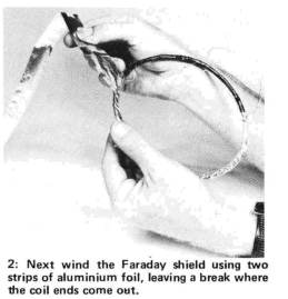
Next, wind the Faraday screen. Cut some aluminium kitchen foil into
strips about 15 mm wide and wind this around the coil to make two layers
but leaving a small gap about 5 mm to 10 mm wide where the coil ends
come out. It is very important that the two ends of the Faraday shield
do not connect as this would make a 'shorted turn' and the coil would
not work as intended.
To secure the foil tightly around the coil and to make connection to
the shield, wind a length of tinned copper wire around the shield with
about a 10mm pitch (i.e: about 10mm between successive turns). The end
of this wire is taken out at the same place as the coil connections.
Now wind another two layers of insulation tape around the whole
assembly. Drill a 3 mm hole in the side of the pot stand and then press
the coil down into the rim with the connecting wires adjacent to the
hole. Pass the wires through the hole. Pour quick- setting epoxy over
the coil to hold it in place.
The search head is mounted to the stem using two right-angle brackets
and a bolt passed right through the end of the stem. Small pieces of
metal here don't seem to adversely affect the operation of the detector.
Solder the coil connections to the twin shielded cable, the Faraday
shield connecting to the cables shield, and glue the cable and wires
underneath the pot stand to hold them rigid. If you wish, the
'underside' of the pot stand may be completely filled with epoxy.
Wind the cable around the stem to keep it mechanically rigid and pass it
through a grommeted hole in the box. Terminate the cable to the pc
board.
Using it
When the construction is complete, turn on the detector, advance the
volume control and rotate the coarse frequency knob. You will hear a
number of 'heterodynes' or beats, one being very strong. This heterodyne
is the one commonly used, the others being odd multiples of the
reference signal beating with multiples of the search oscillator. You
may find that some of these weaker signals are more sensitive to buried
objects than the stronger one.
Set the fine frequency control to midrange and set the course frequency
control to near the strong heterodyne with the search head held away
from the ground. Lower the detector to the ground and you will notice a
frequency shift. This is the effect of the ground and will vary between
different types of soil. Use the fine frequency control to set the beat
to a low pitch and sweep across the surface. A metal object will cause a
change in the pitch which is clearly audible.
The ear is more sensitive to changes in pitch at low frequencies than at
high frequencies and thus it is best to adjust the fine frequency
control to a low pitch that can be heard at a comfortable volume from
the loudspeaker.
Theoretically, the frequency of the search oscillator should increase
when a non-ferrous object comes within range of the search coil and
decrease when a ferrous (or diamagnetic) object is within range. This
effect is difficult to detect in practice as eddy currents in ferrous
materials swamp the effect and they react much the same as non-ferrous
metals. However, minerals such as hematite may show the effect. With the
search oscillator set on one side of zero beat, metal objects near the
search coil will cause the pitch to increase, while magnetic minerals
will cause the pitch to decrease. With the search oscillator set to the
other side of zero beat, the opposite will occur.
You could try a few experiments to show up this effect.
Enough theorising. In general operation, try to keep the search head a
constant distance from the ground and sweep from side to side in a
regular pattern. The right technique is easily developed with a little
practice.
There are a number of books on metal detecting available and these show
the sort of techniques the successful treasure hunter employs.
| HOW IT WORKS The beat frequency metal detector employs two oscillators: a very stable reference oscillator and a search oscillator. The search oscillator uses a tuned circuit designed to be influenced by metal or mineral objects which are brought into its field. The two oscillators are adjusted so they are harmonically related and fed to a mixer. When the search frequency is adjusted so the reference frequency fed to the mixer is eight times the search frequency, the output of the mixer is zero. The search frequency is slightly adjusted so that an output appears from the mixer which is the difference between the two input frequencies. This can be adjusted to an audio tone. When a piece of metal or mineral is brought near the search coil the frequency of the oscillator varies, which in turn varies the output frequency from the mixer. The change in pitch can easily be heard from the speaker. The reference oscillator employs a crystal in a CMOS oscillator circuit using one gate from IC2a. The resistor R6 biases the gate into its linear region. IC2 b, c and d, are used as buffer stages to prevent oscillator pulling and to further square its output waveform. Two flip-flops, IC3a and b, divide the reference signal by four to 890 kHz. The search oscillator uses a discrete transistor in grounded base configuration, with the search coil in the collector. Using the coil in the collector increases the strength of the field around the coil and hopefully overcomes some of the losses in the ground. Feedback is set by the ratio of C2 to C3 from collector to emitter and their value determines the frequency of the oscillator. The base is grounded at RF by C4. By varying the bias on the transistor the inter-element capacitances can be varied. This varies the oscillator frequency as the transistor capacitances form part of the strays in the LC circuit. RV1 and RV2 provide fine and coarse frequency control. The resistors R8 and R9 limit the maximum and minimum voltage on the base to prevent over-dissipation in the transistor or drop-out of the oscillator. The output of the search oscillator is fed to a Schmitt trigger, consisting of IC1a and b, where it is squared and further buffered by IC1c and d. The search frequency is then fed to the mixer. Both oscillators are decoupled from each other by supply line decoupling R1, C1 and R5, C6. The mixer consists of half a dual-D flip-flop. The search and reference frequencies are fed to the clock and D inputs respectively. The flip-flop looks at the reference oscillator (D on every positive transition of the search oscillator clock), and transfers this level to the Q output until the next clock transition. If the two oscillators are exactly evenly harmonically related (i.e: 2nd. 4th, 6th, or in our case 8th, harmonic) the D input will always be the same level at each clock pulse. The output from the mixer at the Q pin will always be the same — no pulses. However, if the search frequency is varied and the D and clock inputs are no longer harmonically related but are changing in phase with respect to each other, after a few clock pulses the D input will no longer be the same — the output will change state. The effect of all this is to produce a chain of square waves at the Q output, the frequency of which is eight times the change in frequency of the search oscillator. Capacitors C8 and RV2 form a differentiating network which feeds a pulse to the audio amplifier, Q2, for each output transition from the mixer. Each cycle from the mixer produces two pulses in the speaker. If the frequency of the search oscillator is shifted one hertz the output of the mixer changes by eight hertz, producing an output of eight pulses per second in the speaker. |
| PARTS LIST Resistors all 1/2W, 5% R1 100R R2 1k R3 100k R4 1M R5 100R R6 10M R7 22k R8 R9 4k7 Potentiometers RV1 10k lin RV2 100k lin RV3 100k log switch pot Capacitors C1 100ngreencap C2 1n styroseal C3 5n6 styroseal C4 100n greencap C5 47p ceramic 06 100n greencap C7 10p ceramic C8 100n greencap Semiconductors Q1, Q2 BC548, BC108, etc. IC1, IC2 . . . . 4001B IC3, IC4 . . . .4013 Miscellaneous SP1 8 ohm speaker B1,B2 9 Volt battery (type 216) Xtal NTSC colour xtal Metal Detector PC board Length of twin shielded cable, plastic pot stand (approx 150 mm dial, length of steel or aluminium tube (approx 600 mm long, 20 mm dia), length of plastic rod or wood dowel to fit inside pipe (approx 200 mm long), 0.4 mm enamelled wire, aluminium foil, Araldite, box to suit (approx 105 x 125 x 75 mm), three knobs, battery clips, insulation tape, two right-angle brackets. |
Matchless
Metal Locator
by Thomas Scarborough
Want to find a fortune? Buried treasure, perhaps? Lost coins on the beach? Or perhaps you fancy earning some pocket money finding other people's valuables. Either way, this project should really interest you. It's an el-cheapo induction balance (IB) metal locator that delivers surprisingly good performance.
An induction balance (IB) metal locator has a good depth of penetration and distinguishes well between ferrous and non-ferrous metals. It is also capable, to a large extent, of rejecting iron and also tin foil This is a boon for anyone who is searching for coins or noble metals.
My aim with this design was to create a 'minimalist' device — one that would work well but without all the bells and whistles of the expensive, commercial designs. I found that it was possible, with just a handful of components, to design a high-quality metal locator.
Simple, but it works
An IB metal locator is usually far more complex than the design shown here.
The reason for the simplicity is that I have dispensed with analogue circuitry, and instead used a digital transmitter and receiver.
As the search coils pass over metal, only digital signals of a certain amplitude break through to a peak detector (IClb). Since these are in the audio range, they are immediately transferred to the piezo sounder or headphones.
On testing the sensitivity of this design in air, with optimal tuning and using a 25mm-diameter brass coin, it gave a clear signal at 150mm, and a 'screaming' signal at 110mm. It was also able to detect a pin at 30mm.
Note that these figures may not apply in the ground,
where depth of penetration will depend largely on the mineralisation
present.
In contrast, the locator is far more reluctant to pick up tin foil. A
tin foil disk of the same size as the brass coin was only detected at
half the distance in air. This rejection of tin foil is due in part to
the metal locator's low frequency, which avoids what is called skin
effect.
Besides this, if the two coils are positioned as described, ferrous
metals (iron) are, to a very large extent, rejected — to such an extent,
in fact, that a 25mm diameter brass coin weighing seven grams looks the
same to the metal locator as a lump of iron weighing 20 times as much.
Large nonferrous objects are detected at half a metre distance and more.
The locator's power consumption is conveniently low. It draws around
10mA, which means that it may be powered off a small 9V battery. If an
alkaline battery is used, this will provide about 48 hours' continuous
use. In my experience, the number of coins that are found on a beach in
an hour or two should easily make up for the cost of batteries!
Finally, while the stability of the locator is not the best, it's by no
means the worst either. Re-tuning is necessary from time to time,
especially in the first few minutes of use. One soon becomes accustomed
to giving the Fine Tune knob an occasional tweak — perhaps with every 40
or 50 sweeps of the search head.
Circuit description
The search head of a typical IB metal locator contains two coils: a
transmitter (Tx) coil and receiver (Rx) coil.
In this case, the Tx coil is driven by a square wave oscillator, which
sets up an alternating magnetic field in the coil. The Rx coil is then
positioned in such a way that it partly overlaps the Tx coil. By
adjusting the amount of overlap, a point can be found where the voltages
in the Rx coil 'null' or cancel out, so that little or no electrical
output is produced. A metal object which enters the field then causes an
imbalance, resulting in a signal.
The transmitter (IC1a) is a standard 555 oscillator configuration, using
one half of the ICM7556IPD dual low power CMOS version of this IC.
Do NOT use the NE556N IC, by the way.
IC1a oscillates at about 700Hz, determined by R/C components around pins
1, 2 and 6. The 680R resistor limits the current passing through the Tx
coil.
The receiver section (IC1b) is preceded by a simple
yet sensitive preamplifier stage, based on Q1, which amplifies the
signal received from the Rx coil. This is fed directly to IC1b, which is
used here as a high-performance sine-square converter. Its input at
pins 8 and 12 is biased by the divider formed by the 10k resistor and
pots VR1-VR3, so that only pulses of a certain amplitude break through
to output pin 9.
There is a point at which, with careful adjustment, the signal is just
breaking through in the form of a crackling sound. When the locator's
output is adjusted to a fast crackle, the presence of metal turns this
into a 'scream'. This is heard from the piezo sounder or through
standard headphones. The 7556 IC allows up to 100mA of output current,
therefore no further amplification is required.
Winding the coils
The one drawback to any IB metal locator design is its need for two
coils, which must be very carefully and rigidly positioned in relation
to one another. Sometimes there's no room even for a fraction-of-a-millimetre
error in positioning these coils. While this particular design makes
things easier than usual, the placement of the coils will still require
some patience. On the other hand, the winding of the coils is relatively
easy. Each coil also includes a electrostatic (Faraday) shield, which
helps to minimise ground effect.
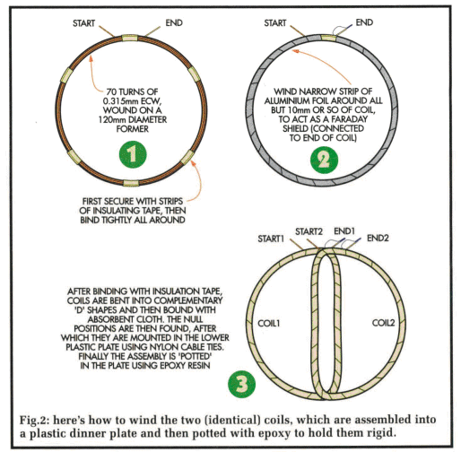
The winding of the (identical) coils is not critical and a little give
and take is permissible.
I used 30SWG (0.315mm) enamelled copper wire, winding 70 turns on a
circular former, 120mm in diameter.
I created the former with a sheet of stiff cardboard with 12 pins stuck
through it at a suitable angle (the heads facing slightly outwards). The
coil was wound clockwise around the pins, then temporarily held together
with stubs of insulating tape passed under the coil and pressed together
over the top. The coil may be jumble-wound (that is, you don't have to
wind the turns on side-by-side in neat layers).
Once this has been done, the pins are removed, and a second coil is
wound in the same way. In each case, mark the beginning and end wires.
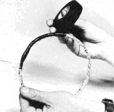
Each coil is then tightly bound by winding insulating tape around its
entire circumference.
Now we add a Faraday shield to each coil. This is accomplished with some
long, thin strips of aluminium foil. First scrape the enamel off each
coil's end wire. Solder a 100mm length of bare wire to the winding wire,
and twist this around the coil, over the insulating tape. This provides
electrical contact for the Faraday shield.
Beginning at the base of this lead, the foil is wound around the
circumference of the coil, so that no insulating tape is still visible
under the foil but the foil should not complete a full 360°. Leave a
small gap (say 10mm) so that the end of the foil does not meet the start
after having gone most of the way around. Do this with both coils. Each
coil is now again tightly bound with insulating tape around its entire
circumference.
Attach each of the coils to its own length of quality single-core
screened audio cable, with the Faraday shield in each case being
soldered to the screen. Do not use stereo or twin-core microphone wire
to run both leads together; this may cause interference between the
coils.
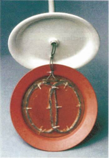
Gently bend the completed coils until each one is reasonably flat and
circular, with each end wire facing away from you, and to the right of
the beginning wire. Now bend them further until they form lopsided ovals
like capital Ds (see Fig. 2). The backs of the Ds overlap each other
slightly in the centre of the search head. This is the critical part of
the operation, which we shall complete after having constructed the
circuit.
Last of all, wind strips of absorbent cloth around each coil (I used
strips of thin dishwashing cloth such as Chux), using a little
all-purpose glue to keep them in place. Later, when epoxy resin is
poured over the coils, this cloth meshes the coils into the resin.
Construction
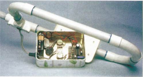
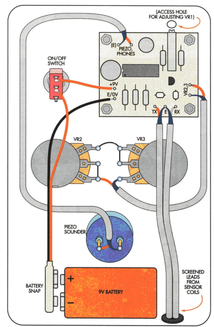
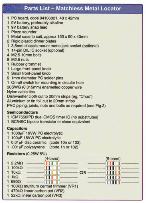
The PC board of the Matchless Metal Locator measures 48mm x 42mm, and is
coded 04106021. There are not many components, so it should be easy to
assemble the board using the PC board overlay diagram in Fig. 3.
With the exception of the CMOS IC, component values and types are not
critical. The one critical component is the ICM7556IPD CMOS IC. I also
tried the TS556CN IC in this position — it worked, but not as well.
Begin board assembly by soldering the nine terminal pins, the 14-pin
dual-in-line socket for IC1 and the resistors. Continue with the
capacitors, diodes and Q1.
Once soldering is complete, carefully check the board for any solder
bridges, then use some short lengths of quality screened microphone wire
to attach the piezo sounder, VR2 and VR3, with the screen (or braid)
always being wired to 0V. If you wish, add a socket for headphones in
parallel with or in place of the piezo sounder. Use insulated hook-up
wire to attach the battery and switch S1, keeping the leads short.
Finally, attach the screened cables from the coils, with the screen
again going to 0V, and insert IC1 in the DIL socket. Note that IC1 is
static sensitive, and requires careful handling (discharge your body to
earth before handling).
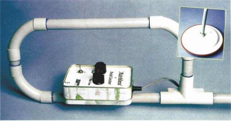
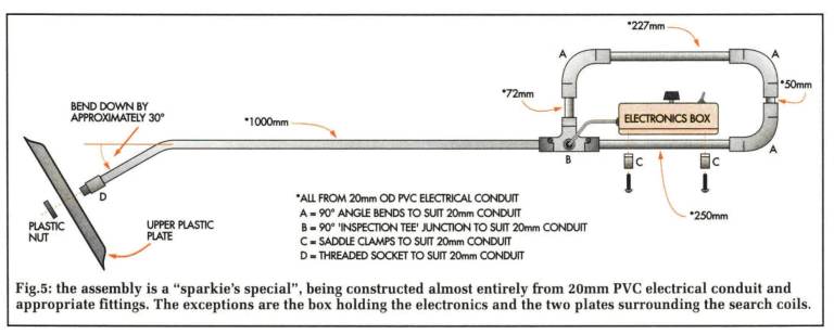
Fig. 5 shows the suggested hardware construction, using PVC piping and
joints. Bend the base of the metal locator's shaft under very hot water
to obtain the angle shown. Alternatively, a swivel joint may be made.
The entire electronics (apart from the search coils) is mounted in a
metal case, ensuring that no part of the underside of the PC board is
touching the case. The adjustment slot for VR1 should be accessible via
a small hole in the case. Mount VR2 and VR3 where quick and easy
adjustment is possible.
A metal case is essential, otherwise the circuit is affected by
electrostatic coupling (or capacitive effects). The metal case is
connected to 0V, through the tab on the copper side of the PC board.
I was unable to obtain a purpose-made metal case in my city (Cape Town),
but found that good quality metal sweet tins were readily available, so
I used one of these. They are also considerably cheaper than similarly
sized electronics enclosures and of course you get the sweets as well!
Setting the coils
A completed PC board is needed before we can 'pot' the coils. These are
potted with epoxy resin in a hard plastic dinner plate, the sort you'd
find in a picnic set. Any plastic plate of suitable size will do, on
condition that it is rigid. (A tip: don't pinch them from the family
picnic set....)
First place the coils on top of one another — ensuring that they are
correctly orientated, with each end wire facing away from you, and to
the right of the beginning wire. Adjust both VR2 and VR3 to their
midpoint. Adjust VR1 to about 90kQ. Then attach a 9V battery and switch
on. The circuit will most likely be screaming; that is, beeping loudly
and continuously. Now slowly move the coils apart. When they are
somewhere past the halfway point, the headphones will fall silent. This
is where the voltages in the Rx coil 'null'. Continue to move the coils
apart. At a precise point just before the coils no longer overlap at all
— the headphones will begin to scream again (there may or may not be a
low-level beep just before this).
It is at this precise point, and not a fraction of a millimetre either
way, that the coils need to be set.
Take an indelible marker pen and mark out holes in the lower plate
around both coils. These holes are used to pass cable ties through, to
hold the coils tightly to the plate. Also use a cable tie to hold the
audio cables to the plate. Use some Blu-tak to tightly seal the holes
underneath the plate before pouring in the resin — epoxy resin can be
very 'runny' and sticks faster than many glues.
Also at this point carefully bend the coils at the centre of the plate
until you reach the exact balance at which there is neither silence nor
screaming in the piezo sounder/headphones, but just a crackle. A little
drift should not matter at this point.
Now you are ready to mix and pour the resin. Use a modest amount of
catalyst, so that there will be not too much heat and shrinkage in the
resin. Pour the resin over the cloth which surrounds the coils, so as to
soak it, and keep on pouring at least until the entire bottom of the
plate is covered with resin.
The circuit may no longer function correctly at this point until the
resin has hardened, so make no more adjustments at this stage, but
switch the circuit off and leave it for 24 hours or so.
I potted two sets of coils (that is, two complete search heads). The
first worked perfectly, precisely as I had set it in the plate. The
second contracted slightly as the resin set, so that no settings of VR2
or VR3 would produce a tone in the headphones. However, this is where
the design of the Matchless Metal Locator shows its flexibility. By
turning VR1 clockwise, the circuit was again functioning normally when
VR2 and VR3 were set to their midpoint.
How to use it
Keep the search head away from all metal — and "noisy" computer
equipment — and switch on. Adjust potentiometers VR2 (Tune) and VR3
(Fine Tune) to their mid-points. Then adjust VR1 with a screwdriver or
plastic alignment tool until the metal locator is just at the point
where a crackle is heard, between silence and a scream (or between a
low-level hum and a scream). Use the tune and fine-tune knobs for any
further tuning.
A fast crackling sound produces the best results. Move a coin over the
search head and the piezo sounder should scream.
In actual use, the adjustment of the metal locator will be affected by
the mineralisation of the ground you are searching, as well as
temperature and voltage variations. So as mentioned earlier,
readjustments to VR3 and VR2 are inevitable from time to time.
That's really all there is to it.
Here is a Metal
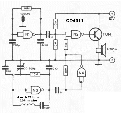
Detector using a CD4011 IC:
The oscillator is built with NAND N1 and a ceramic filter of frequency 470kHz. The second oscillator is with N3 and a LC combination. The frequency
of this oscillator. is adjusted in such way that will produce an audible oscillation of
both frequencies.
Thru N4, the signal from the variable oscillator. is amplified. If the sensor coil L1
is closer to a metal object then it will modify the auto-induction of the coil,
the oscillator is unbalanced and the sound will modify.
Another Simple Metal Detector Circuit:
This circuit is identical
to Fig 7 above and the Metal Detector
in 200 Transistor Circuits
Another Simple Metal Detector Circuit:
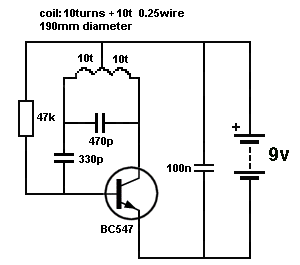
SIMPLE METAL DETECTOR USING A TAPPED COIL
CD 4093 IC Metal Detector
This circuit uses a single coil and nine components to make a particularly
OP AMP METAL DETECTOR
This circuit has
been tested on 23-12-2013. It produces an oscillation at approx 530kHz.
The sensitivity is the same as all the other single transistor circuits, but it
uses a tapped
coil to provide the feedback and this eliminates two components.
sensitive low-cost metal locator. It works on the principle of a beat frequency
oscillator (BFO). The circuit incorporates two oscillators, both operating at
about 40kHz. The first, IC1a, is a standard CMOS oscillator with its frequency
adjustable via VR1. The frequency of the second, IC1b, is highly dependent
on the inductance of coil L1, so that its frequency shifts in the presence of
metal. L1 is 70 turns of 0.315mm enamelled copper wire wound on a 120mm
diameter former. The Faraday shield is made of aluminium foil, which is wound
around all but about 10mm of the coil and connected to pin 4 of IC1b.
The two oscillator signals are mixed through IC1c, to create a beat note.
IC1d and IC1c drive the piezo sounder in push-pull fashion, thereby boosting
the output. Unlike many other metal locators of its kind, this locator is
particularly
easy to tune. Around the midpoint setting of VR1, there will be a loud beat
frequency with a null point in the middle. The locator needs to be tuned to a
low frequency beat note to one or the other side of this null point. Depending
on which side is chosen, it will be sensitive to either ferrous or non-ferrous
metals. 
The circuit above did not work with LM 348 and it was modified as
shown below to work with LM348.
The circuit above works very well and only uses 4 components and two coils. It
is the simplest self-contained circuit and the
Simple Oscillator / Pipe Locator
TDA 0161 METAL DETECTOR IC
This IC is useless. It is expensive and performs very poorly. It will
detect a small coin at 10mm.
Do not use LM 324 - it does not work.
cheapest to build. Adjust the two coils until a "motor-boat sound" is produced.
This will increase when a coil is passed over the coils.
The frequency of the two oscillators was measured as 108kHz.
Checked and tested: 25-12-2013
Sometimes the need arises to construct a really simple oscillator. This
could hardly be simpler than the circuit shown here, which uses just three
components, and offers five separate frequencies. Due to the reactance of the 100-µH inductor and the
propagation delay of the internal oscillator, oscillation is set up around 5MHz. When this is divided down, Stage 14 approaches the frequency of 260Hz.
The Simple
Oscillator / Pipe Locator draws around 7mA from a 9-12 V DC source.
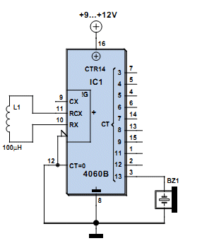
Simple Oscillator/Pipe Locator Circuit Diagram
From: Francisco
The pipe detector using CD4060BE with 150uH
inductor didn't seem very useful to me because the beep tone only changed when
the inductor would actually touch metal.
The inductor has to be as "open" as possible, meaning the coil has to be as
large as possible with the flux being able to escape to the surroundings. In
other words, the flux-path cannot be a good quality magnetic path as any
surrounding magnetic object will not change, remove, upset, the magnetic flux.
Air cores are the best as they are the most sensitive to disturbance by
introduced magnetic objects.
With this detector you will be detecting the change in frequency of a 260Hz
tone. Because the frequency is being divided by 14 stages of division, the
actual frequency-change at the coil will need to be many hundreds of cycles and
this makes this type of detector very insensitive.
All the other detectors compare the frequency of the coil with a fixed frequency
and as soon as the frequency shifts by one cycle per second, the result is
passed to the output. Thus they are over 1,000 times more sensitive. This
circuit shows how NOT TO DESIGN a metal detector.
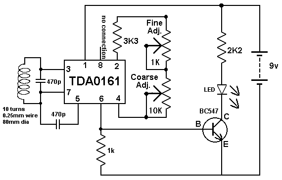
Don't waste your time and money on this circuit. I built it to prove it is
worthless.
Here are some circuits that perform better than a TDA 0161 IC:
This circuit is
our Metal Detector MkII
circuit:
Buy a kit:
Metal Detector kit MkII
$15.00 plus postage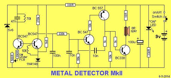
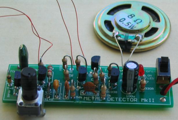
Buy a kit for
Metal Detector kit MkII.
$15.00 plus $6.50 postage.
Nail Finder
Kits for
Metal Detector kit - Nail Finder $17.00
plus postage
The Metal Detector kit also comes as a Nail
Finder.
A Nail Finder head is connected to the Metal Detector PCB as shown in the
following circuit:
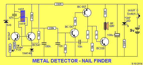
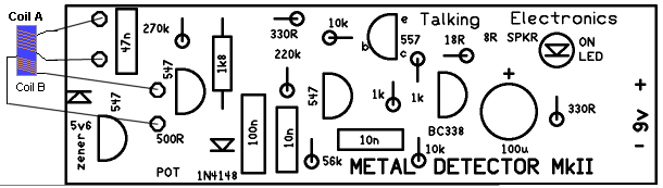
Connecting the Nail Finder head
to the PCB
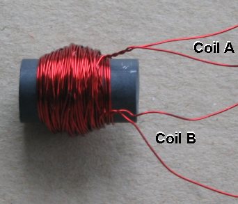
The Nail Finder head
Kits for Metal Detector kit - Nail Finder $17.00 plus postage
555 METAL DETECTOR
MODIFYING THE CIRCUIT
Click HERE for larger image
Here is a discussion on how a number of
oscillators work and the surprising 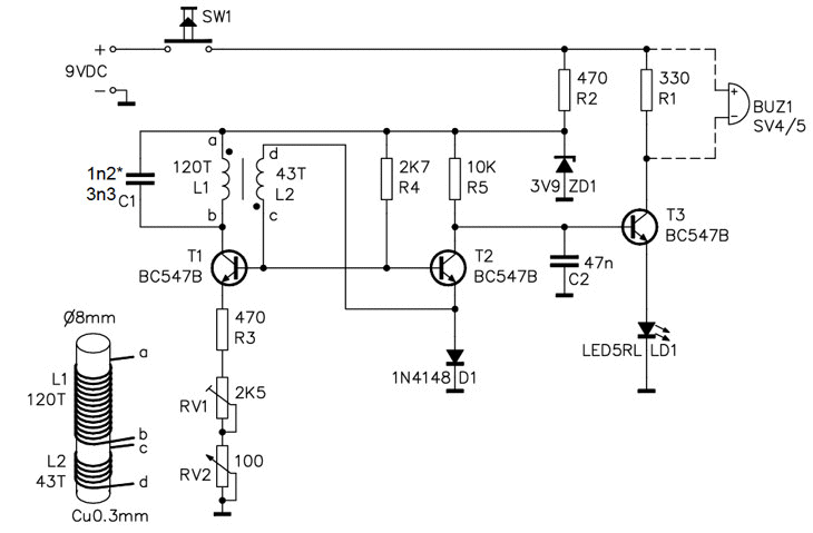
This is a simpler version of Metal Detector MkII with LED readout. It uses a
ferrite rod with 120 turns and 43 turns.
But it is not as sensitive because you are only altering the magnetic flux ON
THE OUTSIDE of the coil, whereas the
magnetic flux on the INSIDE of the coil is more-concentrated and more-sensitive
to disturbance.
Here is a Metal Detector using two 555 IC's:
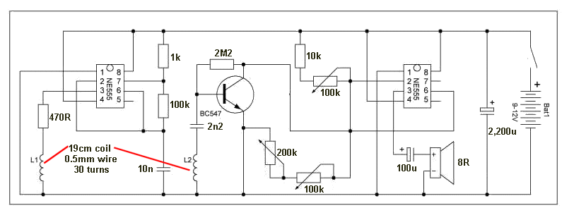
The large coils may make the circuit worth building. The author says:
able to detect a coin at a
depth of up to fifteen centimetres, larger objects up to eighty centimetres.
Here is the website:
https://homemade.metaldetectorsforgold.net/Simple_metal_detector_two_chips_NE_555.html
And here is the 4MB .zip file with all the images:
https://www.metaldetectorsforgold.net/wp-content/uploads/Simple-metal-detector-on-two-chips-NE-555.zip
The author described the circuit incorrectly and I will provide the correct
description.
The circuit is no more than a single coil being pulsed from a 555 running at a
frequency determined by the 10n and 100k resistor.
This frequency is "pumped" into the first coil.
The second coil merely taps off a small amount of the signal due to the
overlapping of the coils. The same effect could have been provided by a 10n
capacitor connected to the top of the first coil.
When the coil detects a metal object, the frequency changes and this is
amplified by the transistor. The amplitude of the signal also reduces.
The second 555 is set with the input at mid-rail, so that when the signal either
changes frequency or reduces in amplitude, the effect is passed to the speaker.
The first 555 is performing the task of a single transistor oscillator but the
second 555 is providing considerable amplification, equal to 3 or 4 transistor
stages. But 555 IC's are only 10 cents and the whole circuit is very cheap to
build.
Talking Electronics has a matrix board for two 555 chips and a pot. You can use
this prototyping board for this project and it will make construction fairly
easy.
You have to look carefully at every circuit you find on the web and see what the
stages are doing and work out if a simpler design can be produced. Prove
this by making the 2-coil circuit and then removing the second coil. The only
way to know if a circuit is good or bad is to make lots of them.
METAL DETECTOR WITH PRINTED COIL
Here is a metal detector kit with
a rectangular coil made by etching a continuous track on a printed
circuit board. The track starts at the outside of the top of one side of
a double-sided PC board and makes loops (square loops) towards the
centre, A via (a feed-through from one side of the board to the other
side) in the centre of the board takes the track to the other
side of the board and the same set of tracks are on the underside.
This produces about 50 turns. It does not matter if the loops are round
or square - the result is about the same, but the whole concept is much
less effective than 50 turns of wire - as you see in the discussion
below.
The kit is very nicely made and comes with a plastic case.
It is supplied by IC STATION:
http://www.icstation.com/product_info.php?products_id=3750#.VKU-cclTSE4
and costs about $5.00 posted.
BUT
the printed circuit coil does not produce a very sensitive "detection."
If you have ever wanted to know if a printed circuit coil works as a
detector for MAGNETIC DISRUPTION, build the kit. The magnetic flux is
widely distributed over a very large area and not very much flux is near the object being detected. That's why it is so INSENSITIVE.
It is just able to pick up a nail in the centre of the coil.
The clever part of the circuit is the single coil. The single coil is
actually TWO coils with a tapping at one turn. You have to look very
carefully at the board to see the coil is tapped at one turn and this
turn is actually producing an out-of-phase output (called feedback). The circuit
WILL NOT WORK if this feature is not included.
The single turn is taken
to the base of the first transistor via a 2n2 capacitor. The value of
the capacitor is not important. It simply connects the signal to the
base of the transistor. The number of turns are not important either.
You can add any number of turns and see how many turns are needed to
produce a signal to activate the first transistor. In this case a single
turn will produce sufficient amplitude as the base is turned on the by
the 220k and the signal just has to add to this voltage.
What this means is this: The signal emerging from the single turn is
out-of phase with the output of the other end of the coil. In other
words, the signal is dropping when the other end is rising. Or, to put
it another way, it is rising when the other end is falling.
This means the signal can be used to turn on the first transistor to
create POSITIVE FEEDBACK. This feedback turns the first transistor
ON more and more and this provides the pulse of energy to feed the tuned
circuit.
This arrangement replaces two separate coils. To explain how the circuit
works, we can use two separate coils:
On the diagram, a second coil (blue) has been added. Remove the link to
L1 and connect the coil to C2. is picked up by the
blue coil and passed to the base of the first transistor.
The first transistor amplifies this signal and passes it to the tuned
circuit to amplify the effect by providing a
pulse of energy at exactly the right time to increase the amplitude of
the waveform.
The gain of the first transistor is adjusted by varying the resistance
on the emitter so the whole circuit is just at the point of
oscillating.
When an object is placed in the centre of the coil, some of the flux is
passed into the metal object and is lost. This means the blue coil does
not see the same amplitude and the first transistor cannot provide the
second coil with enough energy to keep it oscillating.
The feedback winding produces a 10mV sinewave @ 1MHz when the circuit is
at the critical point of being "upset" and when a metal object is added,
the waveform changes and the whole circuit stops oscillating (actually reduces in amplitude) and the second transistor is
turned off slightly. This allows the 2k2 resistor to pull the base of
transistor 3 towards the 0v rail and turn ON the buzzer. The
problem is this: only a few turns are near the metal object and this
makes the circuit very insensitive.
However we can remove L2 and link C2 to L1 and the circuit will work
exactly the SAME - with ONE tapped WINDING.
This is the SKILL of seeing how a circuit works and being able to
simplify it.
The circuit can be made much more sensitive by replacing the printed
circuit coil with 50 turns of wire (0.25mm), 70mm diameter for coil L1
and 5 turns of the same wire for coil L2.
The 100R mini trim pot needs to replaced with 1k mini trim pot.
Turn the circuit ON and the buzzer will squeal.
Place the two coils together and the buzzer will gradually stop.
If not, turn the 5-tun coil over and adjust the mini trim pot until the
buzzer stops.
The circuit is very sensitive to very small changes in the resistance of
the mini trim pot but you can get it to stop squealing and it will
detect a coin at about 5cm when near the centre of the coil.
This is much more sensitive than the original design.
Alternatively, you can create a single TAPPED WINDING.
Start by winding 50 turns and make a knot in the start-wire so you know
the start of the "transformer."
Make a loop (called a "tapping") and wind 5 more turns. Sticky-tape the
turns together.
You now know the start, tap and end of the coil.
Here is the diagram for adding the coil:
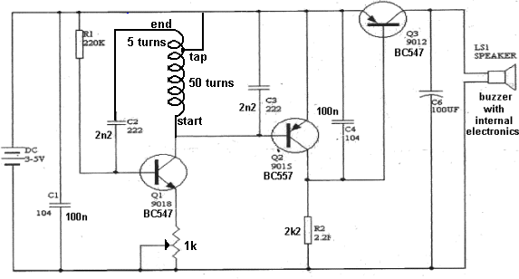
The circuit is not as sensitive as METAL DETECTOR MkII but gives
a good platform for experimenting and understanding oscillators,
feedback and tuned circuits. You can compare the effectiveness of a PCB
coil with a wire-wound coil.
It is pointless learning the theory about these circuits until you have
built at least 10 different designs because the effectiveness works on a
principle called "natural effectiveness" or "natural gain" or "natural
activity" and we call this "Q" or "Quality factor" and this is the
ability of a circuit to produce a very high amplitude from a very small
supply voltage.
This amplitude must also be produced from very small "packets of energy"
and this means any piece of magnetic material entering the "field" will
reduce the amplitude. This important fact has NEVER been mentioned in
any text book ANYWHERE. It is the absolute BASIS of metal detection.
Here's the main reason why this circuit is not very sensitive.
The amplitude of the signal cannot rise above 600mV (in one direction)
because this is the maximum between emitter and base of the PNP
transistor. This allows the signal to produce a peak-to-peak waveform of
1200mV. And that's what is does. The single-turn feedback winding
produces a maximum of about 20-24mV and the (printed circuit - printed
circuit board) coil has a total of 50
turns.
This produces very little electro-magnetic radiation and the circuit is
not very sensitive.
Another reason for the insensitivity is the way the coil is constructed.
The coil is called an AUTO TRANSFORMER and this means it is a
transformer with a single winding that is tapped.
It works exactly the same as a transformer with two windings. A 50-turn
winding and a 5-turn winding.
This type of transformer has a feature called TURNS RATIO. The ratio is
10:1 and the output of the 5-tuns is one-tenth the voltage on the main
winding.
This type of transformer is normally used as a CURRENT transformer
because the current out the 5-turn winding can be 10 times the current
supplied to the main winding.
But we are using it as a voltage winding. But this winding is only 10%
as sensitive as the main winding.
If the voltage drops by 10mV on the main winding, the "feedback winding"
only sees 1mV. In other words it is not a very sensitive way to detect
the presence of a metal object.
So, you can see . . . this circuit has a number of faults and
limitations that make it a poor design.
The Metal Detector MkII kit has a ratio of 50:70 and is much more
sensitive.
Where does all this "signal" or "noise" or "activity" come from ?
What makes the "signal" in the first place?
The signal or waveform produced in the coil comes from the natural
ability of the coil and 2n2 (across it), producing a waveform without
any other components.
That's right. Whenever a coil (called an INDUCTOR) and a capacitor
(across it) receive a short pulse of energy . . . and then there
is nothing connected to the lower terminal of the combination, the two
components will produce a sinewave signal. The two components are called a
TUNED CIRCUIT (parallel tuned circuit) or RESONANT CIRCUIT (a circuit
capable of resonating) or NATURAL
OSCILLATORY CIRCUIT and that is exactly what happens when you turn the
project ON and "pulse" the two components. The only other
component that "boosts" or helps these two components produce
a sinewave is the first transistor. BUT this
transistor DOES NOT PRODUCE the waveform. It just supplies the pulse of
energy at the correct instant in each cycle.
The first transistor turns ON at the beginning of each cycle and
supplies the pulse of energy and then turns OFF. The two components then
produce the smooth sinewave.
The transistor is turned ON by the single-turn or 5-turn feedback
winding. That's how the 1MHz oscillator works.
HOW DOES THE OSCILLATOR KEEP OSCILLATING?
The first transistor is turned on very lightly by the 220k base
resistor. This puts a small current through the coil and expanding flux
is produced. This is the same as INCREASING FLUX. This flux cuts the turn of the feedback winding and a small
voltage is produced . . . . along with a current . .
.that adds to the current supplied by the 220k. This turns the
transistor ON more and the process increases and increases until the
transistor is fully turned ON.
At this point the transistor is fully turned ON and the flux is a maximum
but it is not expanding (or INCREASING) flux and the flux does not cut
the turn of the feedback winding and does not produce a voltage or current. Thus the
voltage on the feedback winding suddenly stops and the transistor is
suddenly turned off to the weak condition provided by the 220k.
The flux produced by the coil starts to collapse and produce a voltage
in the feedback winding that is OPPOSITE POLARITY and now the feedback
signal counteracts the effect of the 220k and turns the transistor OFF
fully.
The flux continues to collapse and it passes all its energy to the 2n2
capacitor. When the signal can no-longer act against the 220k, the 220k
starts to turn the transistor ON a small amount and the cycle starts
again. All this is happening at one million times per second.
What are the three main faults with this circuit?
Answers at end of article
MICRONTA
DELUXE METAL DETECTOR
Here is a very good metal detector from Micronta. The secret of its
sensitivity is the construction of the search coil. Unfortunately I do
not have any details of this and the circuit has been included for
viewing only.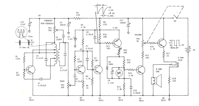
Here
is anther version of the metal detector using a coil that is printed on the
fibre-glass PC board.
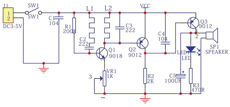
The circuit is not very sensitive. The only reason I can give is the design of
the circuit.
The PCB coil was replaced by a wound coil of 30 turns, 70mm diameter, and one
turn for the feedback.
As the single turn is moved closer to the 25 turns, the active buzzer stops
squealing and the LED turns off.
It is only good for detecting large metal objects at a short distance. The
best result was a 25 cent coin at about 20mm. This is a very poor result.
The coil on the PCB is 26 turns on one side of the board and 26 turns on the
underside, making a total of 56 turns. The inductance was measured at 0.12mH.
The "feedback" winding is just one turn. It must be connected around the correct way. It must deliver a signal that
increases the noise produced by the transistor to produce an oscillator. This
oscillator has a certain amplitude and you control the amplitude by the 1k pot
in the emitter. This amplitude is passed to the second transistor where it is
increased about 200 times and effectively prevents the 100n capacitor being
charged via the 2k resistor.
This keeps the third transistor OFF and the speaker does not produce a noise.
When a metal object is detected by the coil, the amplitude of the magnetic
waves from the 26 turns are reduced slightly and the amplitude of the oscillator
is reduced. This means the second transistor does
not keep discharging the 100n to the same extent and it charges a small amount
via the 2k resistor. This puts a small voltage across the base and emitter of
the third transistor and it turns ON slightly. The speaker is actually an active
buzzer
and it will produce a tone when a small DC voltage is applied to its terminals.
This circuit has about the same sensitivity when the coil is wound with
0.25mm wire and its effectiveness could not be improved. It is the type of
oscillator used in this design that makes the product not very sensitive.
conclusion that one of the oscillators produces results better than all the
others:
Generally, an oscillator is designed to produce a STABLE OUTPUT.
We don't want an oscillator to drift - change frequency - but for Metal Detection, we want the oscillator to be sensitive to outside influence. This makes it very SENSITIVE.
These oscillators have the coil exposed to the surroundings and the turns have a very large diameter.
This type of oscillator is used to detect the presence of a metal object. The metal will alter the inductance of the coil by absorbing some of the magnetic flux and increase or decrease the frequency of the circuit, depending on the type of metal.
There are two types of metal - as far as magnetism is concerned. Magnetic and non-magnetic.
But when an oscillating magnetic field is present, another feature is present.
All metals that conduct electricity will produce eddy currents when exposed to an oscillating magnetic field and this will absorb some of the magnetic flux.
This will increase the inductance of the coil and reduce the frequency.
Most of the oscillator circuits are Colpitts and can consist of 5 to more than 15 components.
The whole idea of the circuit is to make it stable when "sitting around" but allow the slightest magnetic influence to change the frequency.
This is called the SENSITIVITY of the circuit and we will be providing a number of circuits for you to test and compare their sensitivity.
These circuits operate between 100kHz and 500kHz and to detect when they shift by as little as 1Hz, we use a stable reference oscillator. The oscillator is an AM radio. It has an inbuilt 455kHz oscillator and when placed near a Metal Detecting Oscillator, it picks up the signal, (just like a radio station) and produces a whistle. This whistle represents the difference in frequency of the two oscillators.
It is called a BEAT-FREQUENCY or Difference Frequency.
By tuning across the band you will get a lowering in frequency until the whistle stops. At this point the two oscillators are the same frequency or one is a multiple of the other and the difference produces a zero- frequency beat. If a coin is brought near the detecting coil, the change in frequency will be heard.
Even though this arrangement is very simple, it is equal to all the BFO (Beat Frequency Oscillator) Gold detectors on the market.