|
27MHz Field Strength Meter |
|
|
When building 27MHz transmitters (and receivers) it is essential to have a simple piece of test equipment called a FIELD STRENGTH METER to make sure the transmitter is transmitting and to determine the frequency of transmission.
This project has both features.
It is an ESSENTIAL piece of test equipment because you need to know a transmitter is working and hen you need to know it is transmitting at the correct frequency.
If the frequency of the transmitter is slightly different to the frequency of the tuned circuit of the receiver, the two will not communicate and it will be a very difficult job to work out if the problem lies in the transmitter or the receiver.
The reason is due to the TUNED CIRCUIT in the transmitter and receiver.
This allows the transmitter to produce a signal on a very narrow band and the tuned circuit in the receiver performs the same task.
When you are trying to "matchup" the two units, you do not know if the transmitter is higher or lower than the receiver and if you don't have a STARTING POINT, you can spend hours trying to get the two to communicate.
That's why you need a Field Strength Meter.
It lets you now the transmitter is working and allows you to tune it to 27MHz.
Now, you only need to tune the receiver.
THE CIRCUIT
The meter included in the kit has a sensitivity of about 900uA and the only difference you will notice between the 900uA and a 500uA meter is the 900uA will deflect about half the distance "up-scale" In other words, it will have about 50% the sensitivity of a 500uA meter.
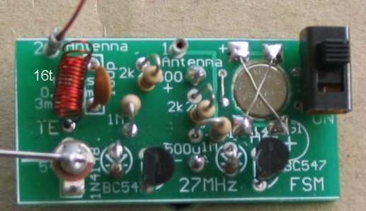
The first section we use when testing a transmitter is the BROADBAND detector. This is identified by Antenna 1. This is called an UNTUNED amplifier and simply picks up RF.
This is designed to let you know the transmitter is working.
But you don't know the frequency of operation.
This is the function of the other circuit.
It is has a TUNED front end consisting of a coil and capacitor in parallel.
When the natural resonant frequency of these two components is the same as the frequency of the transmitter, the voltage produced will be greater than 1.2v and the transistor will turn ON to move the pointer up-scale.
In this case, the two components are not called a TANK CIRCUIT but a TUNED CIRCUIT and they are not loaded AT ALL until the voltage reaches 1.2v. This means it is very easy for them to generate a voltage. You can see the circuit does not provide them with any voltage and so all the voltage produced comes from the RF energy absorbed from the surroundings.
When the antenna is connected to the PC via a pin called a machine pin, a very small signal will be picked up, consisting of all the "hash" in the surroundings. This will deliver a voltage to the coil and capacitor but the signals will be coming at all different frequencies and they will be adding and subtracting so that nothing observable will be produced.
If a transmitter is brought near the antenna, the signal will be larger than all the background "hash" and it will consist of a single waveform (single frequency). It will deliver energy to the capacitor and the capacitor will deliver energy to the coil and the coil will deliver energy back to the capacitor but at a slightly different time to that of the next wave from the transmitter.
The result will be a very small signal being passed from capacitor to coil and back again.
But by adjusting the air trimmer, a position will be reached where the waveform produced by the capacitor and coil will be reinforced by the incoming signal from the transmitter and the waveform will get larger and larger. Eventually it will increase to 1.2v. If the diode is removed, this voltage will be even higher. But the diode drop of 0.6v and the base-emitter drop of 0.6v limits this amplitude to 1.2v and the extra energy produced by the circuit is passed to the transistor to turn it ON.
This section is effectively your reference for a 27MHz transmitter.
That's why the coil must be exactly as supplied in the kit and shown in the photos. Adjusting the spacing of the turns will alter the frequency at which the tuned-circuit resonates and this change will be quite considerable.
FITTING THE ANTENNA
The antenna is firstly placed in position 1 on the board to get an indication that the transmitter is working and then it is taken to antenna point 2.
Rotate the air trimmer and the pointer on the multimeter will rise and fall as the peak of oscillation is reached and passed.
CONSTRUCTION
A kit of components is available from Talking Electronics.
All the components are included in the kit and everything is identified on the board.
The most critical part of construction is the tuned circuit for antenna
point 2.
The coil supplied in the kit has the correct dimensions for a 27MHz
transmitter.
This is very critical and the coil must not be stretched or squashed as
the tuned circuit will not produce a peak amplitude for 27MHz.
Just the last two turns need to be extended to produce 27MHz as shown in
the photo above.
Use fine tinned copper wire to hold the cell in place and make sure the wires do not create
a short-circuit.
CONNECTING THE METER
The PC board is connected to a multimeter via two paper clips.
They are connected to the board at the holes identified by 500uA. The
paper clips are made from spring steel and are very hard. They must not
be cut with delicate side cutters. Simply use a file to score a mark on
the side of the wire and bend it back and forth a few times and it will
break.
Squeeze the paper clip together so it fits down the holes in the
multimeter and makes a good SLIDING connection.
Almost any meter can be used on the 1mA or 0.5mA range.
When you turn the project ON, the meter will show about half-scale
deflection to represent the quiescent current taken by the circuit.
When the antenna detects RF, one of the circuits will turn ON more and
take more current. This will show on the meter.
CONNECTING A BALANCE
METER
The kit comes with a "side reading" BALANCE METER. This is actually
called a MOVEMENT as it is not calibrated, however it has been adjusted
to read upscale and the centre-reading corresponds to 300uA.
Maximum deflection corresponds to 900uA, so the scale is not very
linear. This does not concern us in this project. We just need the meter
to give us a deflection. That's why it is FREE!
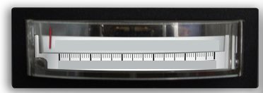
The Balance Meter originally had the pointer positioned in the centre of
the scale so it could deflect up-scale or down-scale. The hair spring
has been adjusted so the needle is now positioned at the zero mark on
the scale and it reads "up-scale."
No SHUNT RESISTOR is needed across the terminals as the sensitivity of
the movement is about 1mA. This is not a very sensitive movement but
that does not matter. It still gives the exact same reading as a very
sensitive movement.
Sensitive movements are only needed for voltage readings, measuring high
resistances and for currents less than 30uA.
This 27MHz link is designed to get you into
understanding the concepts of transmission - it's the place to start.
The 27MHz link consists of a
27MHz
Transmitter - 2-Channel
27MHz receiver
- 2-Channel
27MHz FSM |
|
2 - 2k2 resistors 2 - 1M resistors 1 - 5-30p air trimmer 1 - 100p ceramic 2 - 1N4148 diode 2 - BC547 transistors 1 - 16 turn coil 2 - paper clips for meter 3 - machine pins for antenna 1 - 10cm 0.5mm wire for antenna 1 - AG1 cell fine tinned copper wire for cell 1 - mini slide switch 20cm very fine solder 1 - 27MHz FSM PCB FREE 0-1mA Meter included (see text for description) |
MORE TEST
EQUIPMENT
Talking Electronics has a number of pieces of TEST EQUIPMENT to help in
the design and testing of projects.
Of course you can use a multimeter for most of the testing but some of
the "tricky" faults need a special piece of equipment.
You may only need a LOGIC PROBE once a month, but the project you are
designing will come to a
stand-still if you can't locate a problem.
We designed all these projects because we needed them ourselves.
Add one of them to each order you place with Talking Electronics and eventually you will have the whole
range.
|
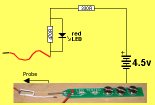
LED TESTER Tests LEDs. $1.50 plus $4.00 post (buy a number of kits and pay only one postage) |
 |
|
CONTINUITY TESTER Only responds to resistance less than 50 ohms. Ideal for digital projects as it tests connections very quickly. $12.50 plus $6.50 post (buy a number of kits and pay only one postage) |
 |
|
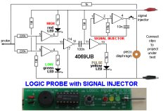
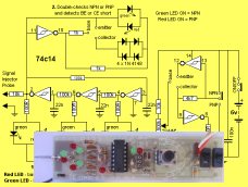
LOGIC PROBE with PULSER
- slimline Detects HIGH and LOW signals on both TTL and CMOS circuits. The piezo allows you to hear low frequency signals and the signal injector (Pulser) will over-ride clock signals to make a circuit operate at a reduced frequency. $8.00 plus $6.50 post |
 |
|
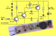
SUPER PROBE 20 different functions. See article for the complete list of functions. $18.00 plus $6.50 post |
 |
|
COMBO-2
TRANSISTOR TESTER Tests transistors and shows the gain of the transistor. Also has Signal Injector probe. $21.50 plus $6.50 post |
 |
|
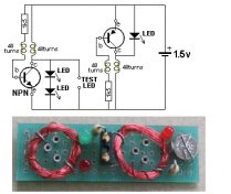
Simple
Transistor and LED Tester - 3 Tests PNP and NPN transistors and LEDs. Also teaches the amazing property of an air-cored coil in producing a high fly-back voltage. $4.00 plus $3.00 postage. (buy a number of kits and pay only one postage) |
 |
|
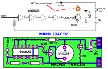
MAINS TRACER Detects 240v AC mains hidden in walls etc. Will also pick up RF signals from a keyboard to show you where Electromagnetic Radiation is coming from and giving you a headache. $10.00 plus $4.50 post |
 |
|
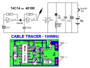
CABLE TRACER
- 100MHz Traces cables when the power is OFF. Uses an FM radio to pickup beeps. $10.00 plus $4.50 postage.
(buy a number of kits and pay |
 |
|
OP-AMP TRAINER and TESTER Teaches how an op-amp works by using pots to control the voltages on the two inputs. $24.50 plus $6.50 post (comes with instructions) |
 |
|
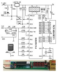
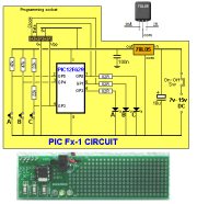
PIC Fx-1 MICRO (8 pin) PROGRAM DEVELOPER and TESTER Learn to program PIC chips. Comes with a pre-programmed PIC12F629 chip with 3 routines. $12.00 plus $6.50 post |
 |
|
Model Railway
POINT MOTOR CONTROLLER and TESTER
CDU-Inline The cheapest CDU project you can get. $8.50 plus $6.50 post |
 |