
Pages 63 to 85
Index
Pages:
1 to 21
Pages:
22 to 41
Pages:
42 to 62
The pages can be printed and collated into a book for easy
reference.
More circuits and projects can be found on TALKING ELECTRONICS
website:
http://www.talkingelectronics.com
Colin Mitchell
talking@tpg.com.au
Tel: 0417 329 788
|
CONTENTS |
|||
|
|
|
|
|
Page 63
40106 OR 74C14 HEX Schmitt Trigger IC
|
|
|
Here are some of the things you can do with the gates in the 40106 Hex
Schmitt Trigger chip:
INVERTING
If the output is required to be the opposite of the circuit above, an
inverter is added:
If a diode is added across the input resistor, the capacitor "C" will be discharged when the input goes low, so the "Delay Time" will be instantly available when the input goes HIGH:
The following circuit produces a PULSE (a LOW pulse) when the input goes HIGH:
Page
64
To invert the output, add an inverter:
To produce a pulse after a delay, the following circuit can be used:
The following circuit produces a tone during the HIGH period. When the output of the second inverter is HIGH, it places a high on the input of the third inverter, via the diode. This is called "jamming" the oscillator and prevents the oscillator from operating. When the second inverter goes LOW, the oscillator will operate.
The oscillator above can be set to
produce a 100Hz tone and this can activate a 2kHz oscillator to produce
a 2-tone output. A "jamming diode" is needed between the third and
fourth gates to allow the high-frequency oscillator to operate when the
output of the low-frequency oscillator is HIGH.
The output can be buffered with a transistor:
Page
65
Extending the action of a push button
The action of a push button can be extended by adding the following
circuit:
To produce a pulse of constant length, (no matter how long the button is pressed), the following circuit is needed:
GATING
Gating is the action of preventing or allowing a signal to pass though a
circuit.
In the following circuit, buttons "A" and "B" are gated to allow the
oscillator to produce an output.
The first two inverters form an "OR-gate." When the output of the gate
is HIGH it allows the oscillator to operate.
The second diode is called the
gating diode. When the output of the second inverter is LOW, the
capacitor is prevented from charging as the diode will not allow it to
charge higher than 0.7v, and thus the oscillator does not operate.
When the output of the second inverter is HIGH, the capacitor is allowed
to charge and discharge and thus oscillator will produce an output. If
the push buttons can be placed together, the circuit can be simplified
to:
PULSER
The 74c14 can be used to produce a 3mS pulses every second. The circuit
is adjustable to a wide range of requirements.
Page 66
2 MINUTE TIMER
Some of the features we have discussed have been incorporated into the
following circuit. The relay is energized for a short time, 2 minutes
after the push-button is pressed. The push-button produces a brief LOW
on pin 1, no matter how long it is pushed and this produces a pulse of
constant length via the three components between pin 2 and 3.
This pulse is long enough to fully discharge the 100u timing
electrolytic on pin 5.
The 100k and electrolytic between pins 6 and 9 are designed to produce a
brief pulse to energize the relay.
TRIGGER TIMER
The next design interfaces a "Normally Open" and "Normally Closed"
switch to a delay circuit.
The feedback diode from the output prevents the inputs re-triggering the
timer (during the delay period) so that a device such as a motor, globe
or voice chip can be activated for a set period of time.
ALARM
In the
following circuit, the gates are used to detect the touch of a door knob
and produce an output that goes HIGH for approx 1 minute.
The output of the above circuit can be taken to an alarm. Open the reed switch contacts and connect the reed switch to the output of the Door-knob alarm.
Page 67
LM 386

300mW amplifier using LM 386
300mW amplifier using LM 386
Page 68
Page
69
A 330k SM resistor

Surface Mount
Resistors
All SM
resistors conform to a 3-digit or 4-digit code. But there are a number
of codes, according to the tolerance of the resistor. It's getting very
complicated.
Here is a basic 3-digit SM resistor:
The first two digits represent the two
digits in the answer. The third digit represents the number of zero's
you must place after the two digits. The answer will be OHMS. For
example: 334 is written 33 0 000. This is written 330,000 ohms. The
comma can be replaced by the letter "k". The final answer is: 330k.
222 = 22 00 = 2,200 = 2k2
473 = 47 000 = 47,000 = 47k
105 = 10 00000 = 1,000,000 = 1M = one million ohms
There is one trick you have to remember. Resistances less than 100 ohms
are written: 100, 220, 470. These are 10 and NO zero's = 10 ohms = 10R
or 22 and no zero's = 22R or 47 and no zero's = 47R. Sometimes the
resistor is marked: 10, 22 and 47 to prevent a mistake.
Remember:
R = ohms k =
kilo ohms = 1,000 ohms M = Meg = 1,000,000 ohms
The 3 letters (R, k and M) are put in place of the decimal point. This
way you cannot make a mistake when reading a value of resistance.
THE
COMPLETE RANGE OF SM RESISTOR MARKINGS:
|
0R1 = 0.1ohm R22 = 0.22ohm R33 = 0.33ohm R47 = 0.47ohm R68 = 0.68ohm R82 = 0.82ohm 1R0 = 1R 1R2 = 1R2 2R2 = 2R2 3R3 = 3R3 4R7 = 4R7 5R6 = 5R6 6R8 = 6R8 8R2 = 8R2 100 = 10R 120 = 12R 150 = 15R 180 = 18R 270 = 27R 330 = 33R 390 = 39R |
470 = 47R 560 = 56R 680 = 68R 121 = 120R 151 = 150R 181 = 180R 221 = 220R 271 = 270R 331 = 330R 391 = 390R 471 = 470R 561 = 560R 681 = 680R 821 = 820R 122 = 1k2 152 = 1k5 182 = 1k8 222 = 2k2 272 = 2k7 |
332 = 3k3 392 = 3k9 472 = 4k7 562 = 5k6 682 = 6k8 822 = 8k2 123 = 12k 153 = 15k 183 = 18k 223 = 22k 273 = 27k 333 = 33k 393 = 39k 473 = 47k 563 = 56k 683 = 68k 823 = 82k 124 = 120k 154 = 150k 184 = 180k |
224 = 220k 274 = 270k 334 = 330k 394 = 390k 474 = 470k 564 = 560k 824 = 820k 105 = 1M0 155 = 1M5 185 = 1M8 225 = 2M2 275 = 2M7 335 = 3M3 395 = 3M9 475 = 4M7 565 = 5M6 685 = 6M8 825 = 8M2 106 = 10M0
|
Page 70
The
complete range of SM resistor markings for 4-digit code:
|
0000 =00R 00R1 = 0.1ohm 0R22 = 0.22ohm 0R47 = 0.47ohm 0R68 = 0.68ohm 0R82 = 0.68ohm 1R00 = 1ohm 1R20 = 1R2 2R20 = 2R2 3R30 = 3R3 6R80 = 6R8 8R20 = 8R2
|
10R0 = 10R 11R0 = 11R 12R0 = 12R 13R0 = 13R 15R0 = 15R 16R0 = 16R 18R0 = 18R 20R0 = 20R 22R0 = 22R 24R0 = 24R 27R0 = 27R 30R0 = 30R 33R0 = 33R 36R0 = 36R 39R0 = 39R 43R0 = 43R 47R0 = 47R 51R0 = 51R 56R0 = 56R 62R0 = 62R 68R0 = 68R 75R0 = 75R 82R0 = 82R 91R0 = 91R
|
1000 = 100R 1100 = 110R 1200 = 120R 1300 = 130R 1500 = 150R 1600 = 160R 1800 = 180R 2000 = 200R 2200 = 220R 2400 = 240R 2700 = 270R 3000 = 300R 3300 = 330R 3600 = 360R 3900 = 390R 4300 = 430R 4700 = 470R 5100 = 510R 5600 = 560R 6200 = 620R 6800 = 680R 7500 = 750R 8200 = 820R 9100 = 910R
|
1001 = 1k0 1101 = 1k1 1201 = 1k2 1301 = 1k3 1501 = 1k5 1601 = 1k6 1801 = 1k8 2001 = 2k0 2201 = 2k2 2401 = 2k4 2701 = 2k7 3001 = 3k0 3301 = 3k3 3601 = 3k6 3901 = 3k9 4301 = 4k3 4701 = 4k7 5101 = 5k1 5601 = 5k6 6201 = 6k2 6801 = 6k8 7501 = 7k5 8201 = 8k2 9101 = 9k1
|
1002 = 10k 1102 = 11k 1202 = 12k 1302 = 13k 1502 = 15k 1602 = 16k 1802 = 18k 2002 = 20k 2202 = 22k 2402 = 24k 2702 = 27k 3002 = 30k 3302 = 33k 3602 = 36k 3902 = 39k 4302 = 43k 4702 = 47k 5102 = 51k 5602 = 56k 6202 = 62k 6802 = 68k 7502 = 75k 8202 = 82k 9102 = 91k
|
1003 = 100k 1103 = 110k 1203 = 120k 1303 = 130k 1503 = 150k 1603 = 160k 1803 = 180k 2003 = 200k 2203 = 220k 2403 = 240k 2703 = 270k 3003 = 300k 3303 = 330k 3603 = 360k 3903 = 390k 4303 = 430k 4703 = 470k 5103 = 510k 5603 = 560k 6303 = 620k 6803 = 680k 7503 = 750k 8203 = 820k 9103 = 910k
|
1004 = 1M 1104 = 1M1 1204 = 1M2 1304 = 1M3 1504 = 1M5 1604 = 1M6 1804 = 1M8 2004 = 2M0 2204 = 2M2 2404 = 2M4 2704 = 2M7 3004 = 3M0 3304 = 3M3 3604 = 3M6 3904 = 3M9 4304 = 4M3 4704 = 4M7 5104 = 5M1 5604 = 5M6 6204 = 6M2 6804 = 6M8 7504 = 7M5 8204 = 8M2 9104 = 9M1 |
|
Three Digit Examples |
Four Digit Examples |
|
330 is 33 ohms - not 330 ohms |
1000 is 100 ohms - not 1000 ohms |
|
221 is 220 ohms |
4992 is 49 900 ohms, or 49k9 |
|
683 is 68 000 ohms, or 68k |
1623 is 162 000 ohms, or 162k |
|
105 is 1 000 000 ohms, or 1M |
0R56
or
R56
is |
|
8R2 is 8.2 ohms |
|
A new coding system has appeared on 1% types. This is known as the EIA-96 marking method. It consists of a three-character code. The first two digits signify the 3 significant digits of the resistor value, using the lookup table below. The third character - a letter - signifies the multiplier.
|
code |
value |
|
code |
value |
|
code |
value |
|
code |
value |
|
code |
value |
|
code |
value |
|
01 |
100 |
17 |
147 |
33 |
215 |
49 |
316 |
65 |
464 |
81 |
681 |
|||||
|
02 |
102 |
18 |
150 |
34 |
221 |
50 |
324 |
66 |
475 |
82 |
698 |
|||||
|
03 |
105 |
19 |
154 |
35 |
226 |
51 |
332 |
67 |
487 |
83 |
715 |
|||||
|
04 |
107 |
20 |
158 |
36 |
232 |
52 |
340 |
68 |
499 |
84 |
732 |
|||||
|
05 |
110 |
21 |
162 |
37 |
237 |
53 |
348 |
69 |
511 |
85 |
750 |
|||||
|
06 |
113 |
22 |
165 |
38 |
243 |
54 |
357 |
70 |
523 |
86 |
768 |
|||||
|
07 |
115 |
23 |
169 |
39 |
249 |
55 |
365 |
71 |
536 |
87 |
787 |
|||||
|
08 |
118 |
24 |
174 |
40 |
255 |
56 |
374 |
72 |
549 |
88 |
806 |
|||||
|
09 |
121 |
25 |
178 |
41 |
261 |
57 |
383 |
73 |
562 |
89 |
825 |
|||||
|
10 |
124 |
26 |
182 |
42 |
237 |
58 |
392 |
74 |
576 |
90 |
845 |
|||||
|
11 |
127 |
27 |
187 |
43 |
274 |
59 |
402 |
75 |
590 |
91 |
866 |
|||||
|
12 |
130 |
28 |
191 |
44 |
280 |
60 |
412 |
76 |
604 |
92 |
887 |
|||||
|
13 |
133 |
29 |
196 |
45 |
287 |
61 |
422 |
77 |
619 |
93 |
909 |
|||||
|
14 |
137 |
30 |
200 |
46 |
294 |
62 |
432 |
78 |
634 |
94 |
931 |
|||||
|
15 |
140 |
31 |
205 |
47 |
301 |
63 |
442 |
79 |
649 |
95 |
953 |
|||||
|
16 |
143 |
32 |
210 |
48 |
309 |
64 |
453 |
80 |
665 |
96 |
976 |
Page 71
The multiplier letters are as follows:
|
letter |
mult |
|
letter |
mult |
|
F |
100000 |
B |
10 |
|
|
E |
10000 |
A |
1 |
|
|
D |
1000 |
X or S |
0.1 |
|
|
C |
100 |
Y or R |
0.01 |
22A is a 165 ohm resistor, 68C is a 49900 ohm (49k9) and 43E a 2740000 (2M74). This marking scheme applies to 1% resistors only.
A similar arrangement can be used for 2% and 5% tolerance types. The multiplier letters are identical to 1% ones, but occur before the number code and the following code is used:
|
2% |
|
5% |
||||||||
|
code |
value |
|
code |
value |
code |
value |
|
code |
value |
|
|
01 |
100 |
13 |
330 |
25 |
100 |
37 |
330 |
|||
|
02 |
110 |
14 |
360 |
26 |
110 |
38 |
360 |
|||
|
03 |
120 |
15 |
390 |
27 |
120 |
39 |
390 |
|||
|
04 |
130 |
16 |
430 |
28 |
130 |
40 |
430 |
|||
|
05 |
150 |
17 |
470 |
29 |
150 |
41 |
470 |
|||
|
06 |
160 |
18 |
510 |
30 |
160 |
42 |
510 |
|||
|
07 |
180 |
19 |
560 |
31 |
180 |
43 |
560 |
|||
|
08 |
200 |
20 |
620 |
32 |
200 |
44 |
620 |
|||
|
09 |
220 |
21 |
680 |
33 |
220 |
45 |
680 |
|||
|
10 |
240 |
22 |
750 |
34 |
240 |
46 |
750 |
|||
|
11 |
270 |
23 |
820 |
35 |
270 |
47 |
820 |
|||
|
12 |
300 |
24 |
910 |
36 |
300 |
48 |
910 |
|||
With this arrangement, C31 is 5%, 18000 ohm (18k), and D18
is 510000 ohms (510k) 2% tolerance.
Always check with an ohm-meter (a multimeter) to make sure.
Chip resistors come in the following styles and ratings:
Style:
0402, 0603, 0805, 1206, 1210, 2010, 2512, 3616, 4022
Power
Rating:
0402(1/16W), 0603(1/10W), 0805(1/8W), 1206(1/4W), 1210(1/3W),
2010(3/4W), 2512(1W), 3616(2W), 4022(3W)
Tolerance:
0.1%, 0.5%, 1%, 5%
Temperature
Coefficient:
25ppm 50ppm 100ppm
CAPACITOR DATA
|
|
|
Capacitors
have five parameters: The maximum
instantaneous voltage a capacitor can withstand. If the
surge voltage is exceeded over too long a period there is a
very good chance that the capacitor will be destroyed by the
voltage punching through the insulating material inside the
casing of the capacitor. If a circuit has a surging
characteristic, choose a capacitor with a high rated surge
voltage. Refers to the
amount of charge that is lost when the capacitor has a
voltage across its terminals. If a capacitor has a low
leakage it means very little power is lost. Generally
leakage is very small and is not normally a consideration
for general purpose circuits. As with
resistors, tolerance indicates how close the capacitor is to
its noted value. These are normally written on the larger
capacitors and encoded on the small ones. C ±.25pF D ±0.5pF E ±1pF G ±2% J ±5% K ±10% L ±15% M ±20% N
±30% Z
+80-20% Capacitor Markings There are two
methods for marking capacitor values. One is to write the
information numerically directly onto the capacitor itself.
The second is to use the EIA coding system. EIA Coding The EIA code works on a very similar principle to the resistor colour code. The first two digits refer to the value with the third being the multiplier. The fourth character represents the tolerance. When the EIA
code is used, the value will always be in Pico-Farads (see
Decimal Multipliers). This expands to: 1 = 1 0 = 0 3 = x 1,000 K = 10% (sec Capacitor Tolerance for listings) Then we combine these numbers together: 1 0 x 1 000 = 10 000pF = 0.01µF, = 10n ±10% tolerance
Example 335K This expands to: 3 = 3 Then we combine these numbers together 3 3 x100,000 = 3,300,000pF = 3,300nF =
3.3uF 10% tolerance. |
Page 74
Page 75
STEAM SIMULATOR
A realistic steam sound can be generated with a
4-transistor directly-coupled amplifier connected to a small
speaker. The “white noise” is generated by the breakdown across the
junction of a transistor and it is activated by a switch made up of
contacts touching the wheel of one of the carriages. As the train
speeds up and slows down, the sound corresponds to the movement.
See Talking Electronics website for the full project.
Page 76
27MHz LINKS
.
Here is the circuit from a 27MHz remote control car. It
is a simple single-channel link that activates the car in the
forward direction when no carrier is being received, and the motor
reverses when a carrier is detected. See Talking Electronics website
for more details – 27MHz Links.
Page 77
This is a single channel receiver, similar to the circuit above.
It can be modified to turn on a “latch” a relay. This means the
relay can be turned on remotely but
it cannot be turned off. The second circuit shows the modification
to turn the relay ON with a short
tone and OFF with a long tone.
The relay can be turned on but
not turned off
The relay can be turned on with a
short
tone and turned off with a long tone
SOLAR CHARGER
This solar charger
can be used to charge a 12v battery from any number of solar cells.
The circuit automatically adjusts for any input voltage and any
output voltage. See Talking Electronics website for the full
project.
Page 78
ARC WELDER

The Arc Welder project is one of many projects for model railroads -
see Talking Electronics
website for the list of projects.
Page 79
Field strength Meter MkII
.
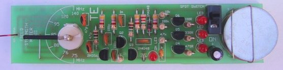
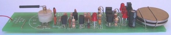
A field strength meter is a very handy piece of test equipment to
determine the output of a transmitter.
Talking Electronics website describes a number of Test Equipment
projects to help with developing your projects.
Page 80
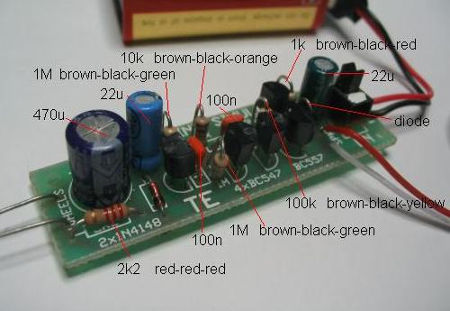
INFINITY BUG
THE SURFACE-MOUNT COMPONENTS OF THE INFINITY BUG
The Infinity Bug sits on a remote phone and when the handset is returned to the rest position, the caller whistles down the line and a very sensitive microphone connected to the infinity bug is activated and any audio within 5 metres is detected.
Page 81
FM BUG
FM
BUG CIRCUIT

FM
TRANSMITTER - 88MHz – 108MHz
The FM Bug is one of
many FM transmitters designed by Talking Electronics, to show how
far a simple transmitter can reach on a few milliwatts. It is most
fascinating to see your
transmitter being detected at 400metres.
3-Transistor
Amplifier
The
surface-mount 3-Transistor amplifier
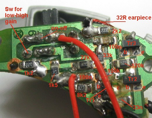
HEARING AID
Page 83
THE AMMETER
(0 - 1uA uses a 1uA
movement)

THE MICROPHONE
Basically there are two different types. One PRODUCES a
voltage and the other REQUIRES a voltage for its operation.
This means you need to supply energy to the second type and this is
very important when you are designing a battery-operated circuit and
need to have a very low quiescent current.
Here is a list of different types of microphones and their
advantages:
|
SUPPLY VOLTAGE REQUIRED: |
|
Electret Microphone - sometimes
called a condenser microphone. Requires about 2-3v @ about
1mA. |
|
Carbon Microphone - also called a telephone insert or telephone microphone. Requires about 3v - 6v. Produces about 1v waveform. Not very good reproduction. Ok for voice. |
|
NO SUPPLY VOLTAGE REQUIRED: |
|
Crystal Microphone - also called
a Piezo microphone. |
|
Dynamic Microphone - also called
a Moving-Coil, Moving-Iron, Magnetic Microphone or Ribbon
Microphone. Very good reproduction. Produces about 1mV. |
Page 84
If a
microphone produces about 20mV under normal conditions, you will
need a single stage of amplification. If the microphone produces
only 1mV under normal conditions, you will need two stages of
amplification.
The circuits below show the first stage of amplification and the way
to connect the microphone to the amplifier.
Connecting an electret
microphone.
The 100n
capacitor separates the voltage needed by the microphone (about 1v)
from the 0.6v base voltage. A good electret microphone can hear a
pin drop at 2 metres. A poor quality electret mic produces crackles
in the background like bacon and eggs frying.
The internal construction
of an electret microphone
Air
enters the electret mic via the top holes and moves the thin mylar
sheet. This changes the distribution of the charges on the plastic
and the changes is passes down the Gate lead to the FET. The FET
amplifies the signal and the result is available on the Drain
lead.
Connecting a Crystal
microphone
The
crystal microphone has an almost infinite impedance - that's why it
can be connected directly to the base of the transistor.
The magnetic microphone has a very low internal resistance and needs
a capacitor to separate it from the base of the amplifying stage. If
it is connected directly, it will reduce the base voltage to below
0.7v and the transistor will not operate.
PIEZO DIAPHRAGM
You can
also use a piezo diaphragm as a microphone. It produces a very
“tinny” sound but it is quite sensitive.
Some diaphragms are more sensitive than others, but the sound
quality is always terrible.
Page 85
MICROCONTROLLERS
Microcontrollers are the way of the future. Most of the basic theory
you will learn for the individual components in this ebook will
become very handy when you need to design a circuit.
As a circuit becomes more and more complex, you have a decision to
make. Do you want to use lots of individual components or consider
using a microcontroller?
Talking Electronics website has a number of projects using
individual components and this is the only way the project can be
designed. But when it comes to “timing” and requiring an output to
produce a HIGH for a particular length of time after an action has
taken place, the circuit may require lots of components.
This is where the brilliance of a microcontroller comes in.
It can be programmed to produce and output after a sequence of
events and the circuit looks “magic.” Just one component does all
the work and a few other components interface the inputs and output
to the chip.
The second special thing about micros is the program.
This has been produced by YOU and it can be protected from “prying
eyes” by a feature known as “code protection.”
This gives you exclusive rights to reproduce the project and all
your hard work can be rewarded by volume sales.
This is the future.
Talking Electronics website has a number of very simple projects
using microcontrollers and these chips all belong to the PIC family
of micros.
These chips are very easy to program as they only have 33 - 35
instructions and they can perform amazing things.
See the Talking Electronics website for project using these micros.
The three micros covered on the website are: PIC12F629, PIC16F84
and PIC16F628. The MCV08A is a Chinese version of the PIC12F629 and
has some extra features and some of the features in the PIC12F629
are not present. But the cost is considerably lower than the
PIC12F629. The Chinese get special deals all the time.
Page 86

HERE IS A PROJECT
USING A MICROCONTROLLER:
SIMON
SIMON PROJECT USING
PIC16F628
SIMON
is the simple game where you repeat a sequence of flashing coloured
lights.
All the “workings” of the project are contained in the program (in
the PIC16F628
microcontroller) and the program is provided on Talking Electronics
website.
See Simon project for more details.
This
completes Data
Book 1.
Look out for more e-books on Talking Electronics website:
http://www.talkingelectronics.com
Sept 2008 Nothing is copyright. You can copy anything.
Colin Mitchell
back to pages:
42 to 62