|
|

There are a number of 6 pin PIC chips with the part number PIC10Fxxx. Some have 256 locations for your program, others have 512 locations. But none have more than 512.
Some have high-temp stability and others have 2 ADC (Analogue-to-Digital-Conversion). All these chips cost about $1.00 in quantity, so we have chosen the cheapest and best. It is PIC10F222T-I/OT. The only more-expensive version is stable to 125°C (ours is 85°C).
The PIC10F222 employs a RISC architecture with only 33 single-word/ single-cycle instructions. All instructions are single cycle (1 μs) except for program branches, which take two cycles. The internal oscillator can be set for 4MHz operation or 8MHz by setting a bit in the configuration-word, during programming.
The PIC10F222 is basically a small version of the PIC12F629 / PIC12F675. It uses the same instruction-set and has 3 in/out lines (and 1 input-only line) as compared with 5 in/out lines (and 1 input-only line) for the PIC12F629 / PIC12F675. About the only added feature of the PIC10F222 is is 4MHz / 8MHz operation.
Here is a list of the main differences between each of the 10F2xx chips. All the other features are the same - all have 1 x 8-bit timer (tmr0) and only 220 and 222 have 2 x ADC and only 204, 206 have a 1 x comparator.
| PIC | Program Memory | Data Memory | |
| 10F220 | 256 words | 16 bytes | 2 Ch ADC |
| 10F222 | 512 words | 23 bytes | 2 Ch ADC |
| 10F200 | 256 words | 16 bytes | 0 |
| 10F202 | 512 words | 24 bytes | 0 |
| 10F204 | 256 words | 16 bytes | 1 Ch Comparator |
| 10F206 | 512 words | 24 bytes | 1 Ch Comparator |
Note: Use only the sixteen data memory files from 10h to 1Fh. The
additional eight files for the 220, 202 and 204 are not available on the
other 3 chips and this will make any programs unusable.
Don't forget the stack has only 2 levels. This means you can call
and then call again from the "called sub-routine" but any calls from
this "called sub-routine" will not work.
Once you go back to the original part of the program (such as Main) you
can make another new call.
DICE PROJECT
A simple dice project using the PIC10F2xx is
shown HERE.
IGNITION/STARTER PROJECT
An Ignition/Starter program using a PIC10F200
is HERE.
MY
SUMMARY
Since the difference in size between a 6-pin and 8-pin surface-mount PIC
microcontroller, is only about 1mm, and the cost is less than 50 cents,
I suggest staying with the PIC12F629 or PIC12F675 (if you want
analogue-to-digital converters).
The PIC12F629 has twice the number of lines for your code (than the
PIC10F222), two more in/out lines, EEPROM and a few other minor
features. For 50 cents, I would concentrate on using the PIC12F629 or
PIC12F675.
There is so much technology available in every area of electronics, that
you must concentrate and limit yourself to selecting a minimum of
technology in each field and concentrating on it. When it comes to
microcontrollers, the PIC family is the best due to the enormous
amount of back-up technology and
examples on the internet.
We have selected the smallest and best micro for all those "starting
projects," and covered it completely with a number of projects, so you
cannot fail.
But, so that know what the smallest micro looks like, here are the
details:
|
PIC10F222T-I/OT (equal to PIC12F675*) * This is the closest equivalent (both have 2 x ADC) |
||||||||||||||||
| General Information | Memory | Pins | ||||||||||||||
|
Flash 1 timer internal osc: 4 or 8MHz ICSP 25mA source/sink per pin |
Microchip Data Sheet |
|
||||||||||||||
| Pinout | ||||||||||||||||
 |
||||||||||||||||
PROGRAMMING THE CHIP BEFORE
SOLDERING
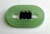
The chip is designed for In-Circuit Programming, but if
you want to pre-program the chips, here is a "carrier" that holds the
chips so they can be programmed before soldering to a project:
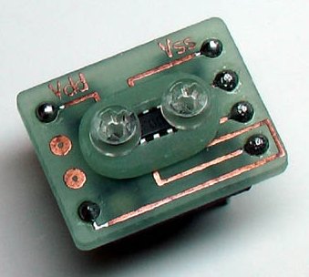
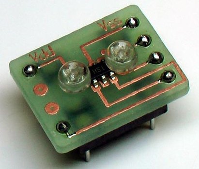
The complete programming
socket
The 6-pin surface-mount PIC10F222 chip can be
programmed by holding it onto a PC board so the pins touch the 5 pads
necessary for programming.
The adapter can be fitted to our programming board
(called Dev-8 board), and the chip
can be programmed with the PICkit2 programmer. The 5 pins
necessary for programming are Vpp, Vdd(5v), ICSPDAT, ICSPCLK and Vss(gnd).
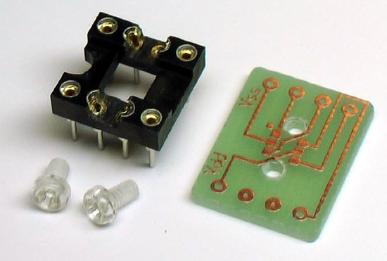
The socket is cut away to allow the screws to pass through the board. The PC board is tapped to take the two screws.
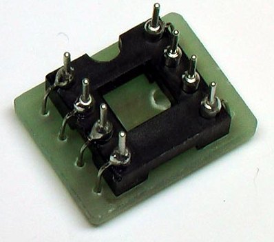
The 8-pin socket is soldered to the PC board with 6 wires.
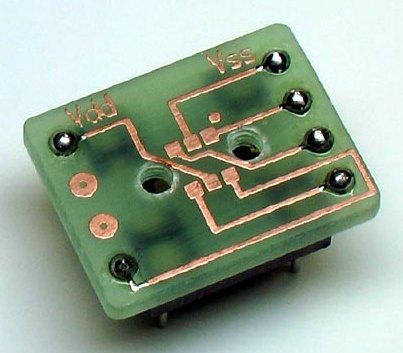
The holder is ready to take the 6-pin chip.
13/1/08