|
SKY WRITER |
|
|
We have seen
many projects using a set of LEDs to produce words "in the air," but
none have the clever feature we have included.
Most of the projects are "shaken in the air" and produce messages that
are "all over the place." But if the words are jumping they are
difficult to read.
Our project solves this. It produces words that re-appear in the same
position so they are easy to read.
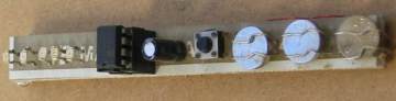
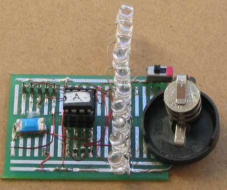
SKY WRITER using
surface-mount LEDs
The secret is called REGISTRATION.
Our design detects the start of the sweep and starts to display the
letters.
This is due to the inclusion of a switch called an INERTIA SWITCH that
detects rapid deceleration and starts the display. More about this
later.
THE CIRCUIT
The circuit is very simple. All the work is done by the micro. We have
produced two different prototypes to show the effect using surface-mount
LEDs and super high-bright white LEDs with two LEDs per output and this
is really effective.
THE INERTIA SWITCH
There are two types of inertia switch. One is a weight on a spring and the other is a ball riding up an incline.
We have used both and they work equally-well and it's just a matter of which type you want to use.
The ball hits the left-side of the
Inertia switch
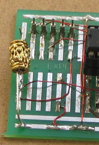
Close-up of the Inertia switch
showing the gap between the contacts.
When the project is moved quickly to the right, the contacts close.
The weight is from a pack of metal
beads - from a bead shop.
To make the inertia switch yourself, it is a small ferrule on a wire. A length of tinned
copper wire wound around it and pulled tight and acts as a spring to keep
the
contacts open. These
contacts are connected to pin 4 of the microcontroller.
You can check the operation of this switch by connecting a LED and
resistor to the supply and waving the PC board. You will find the LED
illuminates at almost the exact same place "in space" making it an ideal
registration-mark for aligning the words.
Once you have a reliable starting-point for creating the display, you can make
almost any effect using the 5 LEDs. There are almost no limits as the display can
be 100
or more pixels long, and 5 pixels
high.
You can change the wording and add more features. To do this you need a
programmer and software. For details on this, see
Pick A
PIC Project.
The table we have used in the program occupies nearly all the space
available (for a table), however you can add other features by studying
some of our other projects.
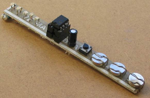 |
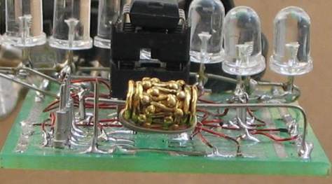
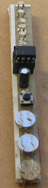 Photos of the two prototypes
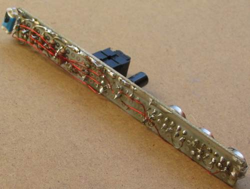 |
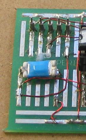
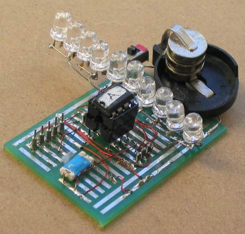 The circuit has two super high-bright LEDs on each output to give a very impressive display. The "inertia switch is shown as the blue rectangular component. It has a ball-bearing that hits both the top and bottom conductors (without jamming) when the ball rolls in one direction. The plastic molding prevents the ball touching both conductors when it rolls in the opposite direction. |
 |
INSIDE THE CHIP
Inside the 8-pin PIC12F629, there are thousands of
transistors, diodes and resistors.
To make things simple, we can consider it has 5 main areas:
Firstly a column of 1024 locations where the program is stored. This
program is written by you and is
called the Program Area. It starts at address 000 to 3FF. The values in
these locations cannot be changed once the chip is "burnt."
The first 256 locations is the only area where a table can be located.
That's why your program uses only a few of these locations and sends the
micro to below the table for the rest of the program.
Another area has a column of 64 files, each capable of being loaded with 8
bits of information. These files are used by you to store information
during the running of the program and are called the User
Files. These Files (or Registers) start at 20h to 5F. The values in
these locations can be altered during the running of the program. The
information is lost when the power is removed.
The third area consists of files that have a special function and
hold bits of information for timers, overflow from an addition and lots
more. These are called Special Function Registers (FSR's).
These values can also be altered during the running of the program. The
information is lost when the power is removed.
There is one file in this list with a surprising feature. It is the
input/output port. It is file 05h. It is called the General Purpose
In/Out (GPIO) file or register or PORT. It has a number of driver
transistors that connect to pins 2 to 7 of the chip. These pins can be
configured as input or output lines with the capability of delivering
25mA to the outside world (pin 4 is an input only line). Then there is a
set of 128 locations in an area called the EEPROM. Information in
these files can be changed during the running of a program and is NOT
lost when the power is removed.
Then there is a microscopic computer that reads each instruction in the
program and carries out the task. Finally there is a working register, called "W," that gets loaded with a
value (called a literal). The Working register is the
transport medium to transfer values from one place to another.
There a lots more things inside the chip such as the program that allows
the chip to be "burnt" (flashed), the program that puts
information into the cells in the EEPROM area and more, but let's keep things simple.
The program you produce by hand is called assembly language and is written
in mnemonics. This produces a .asm file.
This is assembled by an assembler (MPASM - by Microchip) and produces a
.hex file. This file is used by a program called a "Programmer." The
Programmer sends the results to a piece of equipment connected to one of the ports of
your
computer and is called a "Burner." The burner has a socket and the chip
to be programmed
is fitted to the socket and "Burnt" or more-accurately "flashed" - in the
case of the 12F629. The 1024 spaces we mentioned above (and EEPROM) are filled with
your program and when the chip
is placed in a project and turned on, the program is read at the rate of
one million instructions per second by the internal "microscopic
computer."
An instruction can be a simple task such as placing a number (called a
literal) in the "working register" called register "W" or it can
be a more-complex task such as testing a bit in a file and jumping over
the next instruction if the bit is set.
The program for this project has been written by hand using the set of
35 instructions for the chip.
These instructions consists of letters and numbers, with
each letter taken from the first letter of a word such as Shift Left
File (slf) or Bit
Test File xx Skip if Set (btfss), etc.
Each instruction is called a mnemonic.
These are "half-computer,"
"half-English" instructions that both the human and micro understands.
A program for a PIC chip may look unusual at first, but the website
explains the terminology and takes you through
each stage in the development of an idea.
The memory size of 1024 locations (or instructions) may seem small by modern standards but you will find the
chip
is capable of taking the place of quite a number of "old-style"
gating chips and once you see what can be done, you will be designing
almost everything around a microcontroller.
One of the advantages of using a PIC microcontroller is the large amount
of back-up provided on the internet (see PIC Webring) and it has the ability to protect
a program by a feature called "Code
Protecting." By doing this during the burn process, no-one can read or copy the chip.
This gives you some hold over the contents of the program and a project can be
marketed.
If you like this concept, you are ready to start programming.
Writing a program is like writing a novel. You can do anything within
the capability of the chip, and to get some ideas, you can visit Talking
Electronics website for a list of projects created with a PIC12F629.
The next stage is to look at the program for the Sky
Writer and study the sub-routines.
Each sub-routine does a small task and by calling them in quick
succession the
result is very impressive.
If you want to change or improve the program, use our technique of
copy-and-paste where you change only a few instructions at a time.
This project offers three areas for experimentation. It shows how
interface external devices to a microcontroller.
It employs surface-mount technology and covers writing a program for
the simplest chip in the PIC series, the PIC12F629.
THE PROGRAM
Each letter or number to be displayed is made up of a matrix of dots.
All characters are five dots high and can be one dot wide or up to 7 or
more. Each column requires one byte (one location in memory) so some
letters require 7 bytes.
The program has two tables, called Table1 and tabale2. The first table
provides the values for each column of a Character as shown in the
diagram below.
You will notice the value 08 is not present in the left-hand listing
that shows the value for each row. This is due to the way we have used
the values in table1.
Each retlw in table1 contains 8 bits. We are only using 5 of these bits
for the characters. This means we have 3 bits available for other
purposes.
The lowest bit (bit0) is sent to GP0 and this turns on the lowest LED.
The next bit (bit1) turns on the next lowest LED and the next bit turns
on the 3rd LED from the bottom. Since GP3 is not an output pin, we
cannot use it for the display and so this bit is used in the main
program to see if an "end of character" is reached. In the table you
will see it has the value 08. This signifies an end of character. The
next bit (bit4) is used to turn on GP4 and the next bit (bit5) is used
to turn on GP5.
The next bit (bi6) has the value 40h and is used to detect "end of
word."
The highest bit (bit7) has the value 80h and is used to detect "end of
sentence."
Table2 holds the value for the beginning of a letter in table1. As you
can see, table2 contains the words of a sentence and the Main program
starts at the first value and then uses table1 to produce the letter. It
then advances down the table to produce the second letter etc.
In this way the letters are sent to the 5 LEDs to produce a word "in the
air."
Going over this again:
The Main routine goes to table2, and finds the
starting point for a letter in table1.
A letter or number may consist of 1 to 7 columns.
Each column is
displayed for a short period, then the next byte is fetched and
the next column is displayed. In this way a letter or number
is shown on the display.
We can only show a maximum of 8 letters or numbers at a time as more
than this is difficult to read.
The PIC12F629 can only hold up to 256 table values in the first page of
program-memory. A table cannot be located anywhere else.
A few locations are lost at the beginning to send the micro down the
page to the fist sub-routine and all the remaining bytes hold table1 and
table2.
There is no more memory available for more sentences and if you can only
replace the two sentences with something else.
The program can be re-written to hold values in EEPROM where 256 bytes
are available and this is something you can consider. For
"cut-and-paste" instructions on writing and reading EEPROM, see
Dial Alarm-2 project.
You will also need to use some instructions in "set-Up." Using
EEPROM is very technical and the instructions we have used in Dial
Alarm-2 must be copied exactly.
If you want to buy a kit for Sky Writer, the chip comes pre-programmed with a number of sentences.
To change any of the content of the program you will need a
programmer and the software that drives the programmer as well as an
assembler (MPASM) .
All these things are covered in an article:
Pick A
PIC Project.
CONSTRUCTION
A full kit of components is available from
Talking Electronics. It contains
a
pre-programmed chip and surface mount components as well as through-hole
components.
At the moment, surface mount components are not available individually
from electronics supplies and a kit is the best way to get into this
area of construction.
The first components to fit are the surface-mount resistors. The kit
comes with a length of very fine solder and this will make soldering
very easy provided you have a fine tipped soldering iron.
Tin one of the square lands with a very small amount of solder and place
a resistor in position. Hold it in place with a small
Jeweler's screwdriver, by pushing down firmly. Heat up the end
that has been pre-tinned and the resistor will sit on the board.
Now solder the other end very quickly. Let the resistor
cool and go back to the first end.
Repeat this will all the other resistors and the 100n capacitor.
Push the LEDs through the holes until they touch the PC board. Make sure
the shorter lead goes to the negative rail.
Solder the leads very quickly as LEDs are temperature-sensitive.
Fit the IC socket and electrolytic.
The three button cells are fitted to the board by fabricating battery
holders from very fine tinned copper wire contained in the kit.
Firstly solder the two negative contacts by looping the wire through the
board and soldering one end. Now pull the wire with pliers and solder
the other end. Loop the positive wire through the board and solder one
end. Fit the cell under the wire, so it touches the negative wires on
the board, pull the loop tight with pliers and
solder the other end. Solder the other positive wire and the cell will
be kept in position. Repeat the process for the other two cells.
Finally, make the inertia switch as described above.
Move the contacts together so they are separated by a very small gap.
Fit the microcontroller to the socket and the project is complete.
Move the project quickly in a broad arc and a message will appear "in
the air."
GOING FURTHER
How many times have you searched for a birthday or anniversary card and
found nothing to be suitable? Either the message or the pictures are not
appropriate or the music and flashing lights are not "quality."
Most of the time I buy a blank embossed card and fill it out myself.
There is an enormous market for well-designed cards at a reasonable
price.
This project can be made very small and flat and added to a
card so it can been seen in the shop. It could be added to a birthday card or "Get Well"
card and include a simple game or message that displays randomly each
time the card is "waved."
The project needs to be converted to surface mount and the
micro could be a COB (Chip On Board) - as a tiny dob of resin on
mass produced items.
This project is just one idea for a range of cards that are "different from the
rest." The card market is enormous and when you realise most cards
are poorly designed, you have a goldmine of potential.
Other ideas are a combination-lock game, a counter, a ladder
game, and similar things that would make buying a card a
rewarding decision.
Cards are just one area. The market is enormous and include toys and
gimmicks combined with sweets.
The PIC micro gets an idea "off the ground" and you can get your ideas into
production very easily.
It's the starting point you have always wanted.
PARTS
LIST |
|
5 - 82R or 100R
surface-mount resistors 1 - 47k surface-mount resistor "103" 5 - 3mm or 5mm red or white LEDs 1 - 8 pin IC socket 1 - pre-programmed PIC12F629 IC "SKY" 1 - 30cm thick tinned copper wire 1 - 40cm 0.2mm enamelled wire 1 - weight for inertia switch 3 - button cells from 12v lighter battery 1 - 1m very fine solder 1 - Sky Writer PCB |
Here are the files:
SkyWriter.asm
SkyWriter.hex
	;Sky12F629.asm
	;Sky writer with 5 LEDs for PIC12F629  13-5-2010


	list	p=12F629
	radix	dec
	include	"p12f629.inc"

	errorlevel	-302	; Don't complain about BANK 1 registers

	__CONFIG _INTRC_OSC_NOCLKOUT & _MCLRE_OFF & _WDT_OFF
          & _PWRTE_ON & _BODEN_OFF & _CP_OFF & _CPD_OFF ;Internal osc.


			; globals


fileA		equ		20h
fileB		equ		21h
fileC		equ		22h
jump1		equ		23h
jump2		equ		24h


counter		equ		27h
jump2_savd	equ		28h
counter2	equ		29h

status		equ		03h
option_reg	equ 	         81h


	; bits on GPIO

pin7		equ	0	;GP0
pin6	 	equ	1	;GP1
pin5		equ	2	;GP2
pin4		equ	3	;GP3 input only
pin3		equ	4	;GP4
pin2		equ	5	;GP5


	;bits

rp0		equ	5


Start	org	0x00	;program starts at location 000
	goto	SetUp


table1 		;characters

	ADDWF 	02h,1   ;add W to Program Counter
	retlw	00
	retlw 	17h	;A - jump value = 01h
       	retlw 	24h
	retlw 	24h
       	retlw 	24h
	retlw 	17h
       	retlw 	08h
	retlw 	37h	;B - jump value = 07h
       	retlw 	25h
       	retlw 	25h
       	retlw 	25h
       	retlw 	12h
       	retlw 	08h
      	retlw 	34h	;C - jump value = 0Dh
       	retlw 	16h
	retlw 	21h
       	retlw 	21h
       	retlw 	21h
	retlw 	08h
      	retlw 	37h	;D - jump value = 13h
       	retlw 	21h
	retlw 	21h
       	retlw 	21h
       	retlw 	16h
	retlw 	08h
	retlw 	37h	;E - jump value = 19h
	retlw 	25h
	retlw 	25h
	retlw 	21h
       	retlw 	08h
       	retlw 	37h	;F - jump value = 1Eh
       	retlw 	24h
       	retlw 	24h
       	retlw 	20h
	retlw 	08h
	retlw 	16h	;G - jump value = 23h
	retlw 	21h
	retlw 	25h
       	retlw 	25h
	retlw 	06h
	retlw 	08h
	retlw 	37h	;H - jump value = 29h
	retlw 	04h
       	retlw 	04h
	retlw 	04h
	retlw 	37h
	retlw 	08h	;I - jump value = 2Eh
	retlw 	37h
	retlw 	08h
	retlw 	02h	;J - jump value = 31h
	retlw 	01h
	retlw 	01h
       	retlw 	36h
	retlw 	08h
	retlw 	37h	;K - jump value = 36h
	retlw 	04h
	retlw 	04h
       	retlw 	12h
	retlw 	21h
	retlw 	08h
	retlw 	37h	;L - jump value = 3Ch
	retlw 	01h
	retlw 	01h
       	retlw 	01h
       	retlw 	08h
       	retlw 	17h	;M - jump value = 41h
       	retlw 	20h
       	retlw 	20h
	retlw 	17h
	retlw 	20h
	retlw 	20h
	retlw 	17h
	retlw 	08h
       	retlw 	37h	;N - jump value = 49h
       	retlw 	10h
       	retlw 	04h
       	retlw 	02h
	retlw 	37h
       	retlw 	08h
       	retlw 	16h	;O - jump value = 4Fh
       	retlw 	21h
       	retlw 	25h
       	retlw 	23h
       	retlw 	17h
       	retlw 	08h
       	retlw 	37h	;P - jump value = 55h
       	retlw 	24h
       	retlw 	24h
       	retlw 	10h
       	retlw 	08h
       	retlw 	16h	;Q - jump value = 5Ah
       	retlw 	21h
       	retlw 	25h
       	retlw 	23h
       	retlw 	17h
       	retlw 	08h
       	retlw 	37h	;R - jump value = 60h
       	retlw 	24h
       	retlw 	24h
       	retlw 	26h
       	retlw 	11h
       	retlw 	08h
       	retlw 	10h	;S - jump value = 66h
       	retlw 	25h
       	retlw 	25h
       	retlw 	25h
       	retlw 	02h
       	retlw 	08h
       	retlw 	20h	;T - jump value = 6Ch
       	retlw 	20h
       	retlw 	37h
       	retlw 	20h
       	retlw 	20h
       	retlw 	08h
       	retlw 	36h	;U - jump value = 72h
       	retlw 	01h
       	retlw 	01h
       	retlw 	01h
       	retlw 	36h
       	retlw 	08h
       	retlw 	34h	;V - jump value = 78h
       	retlw 	02h
       	retlw 	01h
       	retlw 	02h
       	retlw 	34h
       	retlw 	08h
       	retlw 	36h	;W - jump value = 7Eh
       	retlw 	01h
       	retlw 	01h
       	retlw 	36h
       	retlw 	01h
       	retlw 	01h
       	retlw 	36h
       	retlw 	08h
       	retlw 	21h	;X - jump value = 86h
       	retlw 	11h
       	retlw 	04h
       	retlw 	11h
       	retlw 	21h
       	retlw 	08h	;program looks for 08h as end of character
       	retlw 	20h	;Y - jump value = 8Ch
       	retlw 	10h
      	retlw 	07h
       	retlw 	10h
       	retlw 	20h
       	retlw 	08h	;program looks for 08h as end of character
       	retlw 	21h	;Z - jump value = 92h
       	retlw 	23h
       	retlw 	04h
      	retlw 	31h
       	retlw 	21h
	retlw 	08h	;program looks for 08h as end of character
       	retlw 	00h	;empty space x 2 columns - jump value = 98h
       	retlw 	00h
	retlw 	08h	;program looks for 08h as end of character
	retlw 	34h	;comma - jump value = 9Bh
       	retlw 	08h	;program looks for 08h as end of character
       	retlw 	10h  ;1 - jump value = 9Dh
      	retlw 	37h
       	retlw 	08h
       	retlw 	03h  ;2 - jump value = A0h
       	retlw 	25h
	retlw 	25h
      	retlw 	25h
       	retlw 	11h
       	retlw 	08h
       	retlw 	25h  ;3 - jump value = A6h
      	retlw 	25h
      	retlw 	25h
       	retlw 	12h
       	retlw 	08h
       	retlw 	04h  ;4 - jump value = ABh
      	retlw 	14h
       	retlw 	24h
      	retlw 	37h
       	retlw 	04h
       	retlw 	08h
       	retlw 	34h  ;5 - jump value = B1h
      	retlw 	25h
       	retlw 	25h
      	retlw 	25h
       	retlw 	02h
       	retlw 	08h
       	retlw 	16h  ;6 - jump value = B7h
      	retlw 	25h
       	retlw 	25h
      	retlw 	25h
       	retlw 	02h
       	retlw 	08h
       	retlw 	21h  ;7 - jump value = BDh
      	retlw 	22h
       	retlw 	24h
      	retlw 	30h
       	retlw 	08h
       	retlw 	12h  ;8 - jump value = C2h
      	retlw 	25h
       	retlw 	25h
      	retlw 	25h
       	retlw 	12h
	retlw 	08h
	retlw 	10h  ;9 - jump value = C8h
      	retlw 	25h
       	retlw 	25h
      	retlw 	25h
       	retlw 	16h
	retlw 	08h

		     ;0 - use jump value = 4Fh


table2	;words
	ADDWF 	02h,1   ;add W to Program Counter
	retlw 	29h	;H - Jump1 value for H in table1
      	retlw 	01h	;A
       	retlw 	78h	;V
       	retlw 	19h	;E
       	retlw 	40h	;program looks for 40h as end of word
	retlw 	98h	;empty space
       	retlw 	01h	;A
       	retlw 	40h	;program looks for 40h as end of word
       	retlw 	23h	;G
      	retlw 	60h	;R
       	retlw 	19h	;E
	retlw 	01h	;A
	retlw 	6Ch	;T
	retlw 	40h	;program looks for 40h as end of word
	retlw 	13h	;D
	retlw 	01h	;A
	retlw 	8Ch	;Y
	retlw 	40h	;program looks for 40h as end of word
	retlw 	00h	;0
	retlw 	80h	;program looks for 80h as end of SENTENCE


	retlw 	6Ch	;T - Jump1 value for H in table1
      	retlw 	60h	;R
       	retlw 	8Ch	;Y
       	retlw 	40h	;program looks for 40h as end of word
	retlw 	66h	;S
      	retlw 	4Fh	;O
       	retlw 	41h	;M
	retlw 	19h	;E
	retlw 	6Ch	;T
	retlw 	29h	;H
      	retlw 	2Eh	;I
       	retlw 	49h	;N
	retlw 	23h	;G
	retlw 	40h	;program looks for 40h as end of word
	retlw 	49h	;N
	retlw 	19h	;E
	retlw 	7Eh	;W
	retlw 	40h	;program looks for 40h as end of word
	retlw 	00h	;0
	retlw 	80h	;program looks for 80h as end of SENTENCE


	;Delays

Del_1	movlw 	01h
	movwf 	fileB
DelX	decfsz 	fileA,1		; ,1 denotes the result of the decrement
	goto 	DelX
	decfsz 	fileB,1		;     is placed in the file
	goto 	DelX
	retlw 	00

Del_2	movlw 	0F0h
	movwf 	fileA
DelY	decfsz 	fileA,1
	goto 	DelY
	retlw 	00

Del_3	movlw 	040h
	movwf 	fileB
DelZ	decfsz 	fileA,1		; ,1 denotes the result of the decrement
	goto 	DelZ
	decfsz 	fileB,1		;     is placed in the file
	goto 	DelZ
	retlw 	00

Del_4	movlw 	040h
	movwf 	fileC
Del4A	decfsz 	fileA,1		; ,1 denotes the result of the decrement
	goto 	Del4A
	decfsz 	fileB,1		;     is placed in the file
	goto 	Del4A
	decfsz 	fileC,1
	goto 	Del4A
	retlw 	00

SetUp	bsf	status, rp0 	;Bank 1
	movlw	b'10000110'	;Turn off T0CKI
	movwf	option_reg
	movlw   07h             ;Set up W to turn off Comparator
	movwf   CMCON
	movlw	b'00001000'	;Set GP0,1,2,4,5, as output
	movwf	TRISIO	        ;enable outputs
	bcf	status, rp0	;bank 0
	clrf 	GPIO       	;Clear GPIO of junk


Main	movlw	03h
	movwf	counter2	;each sentence will appear 3 times
	movlw	04h		;each word will appear for 4 "waves"
	movwf	counter
MainA	clrf	jump2_savd	;for table2
MainB	movf	jump2_savd,0
	movwf	jump2
	btfsc	GPIO,3		;looking for close of inertia switch
	goto	MainB
	call	Del_3
	call	Del_3

Main1	movf	jump2,0		;move table2 jump-value into W
	call 	table2
	movwf	jump1		;put the hex value of the letter into jump1
	xorlw	80h		;see if end of sentence is reached in table2
	btfsc	03,2		;bit 2 of file 3 will be SET (=1)
	goto	Main5
	movf	jump2,0		;move table2-jump value into W
	call 	table2
	xorlw	40h		;see if end of word is reached in table2
	btfsc	03,2		;bit 2 of file 3 will be SET (=1)
	goto	Main3		;end of word - add a delay
Main2	movf	jump1,0		;put column-value into W
	call	table1
	movwf	GPIO		;display column value
	xorlw	08h		;see if end of character is reached
	btfsc	03,2		;bit 2 of file 3 will be SET (=1)
	goto	Main4
	call	Del_1		;creates the width of the dot
	clrf	GPIO
	call	Del_2		;creates the space between the dots
	incf	jump1,1
	goto	Main2

Main3	call	Del_3
	decfsz	counter,1
	goto	MainB
	incf	jump2,0
	movwf	jump2_savd
	movlw	04h
	movwf	counter
	goto	MainB

Main4	call	Del_1		;space between the letters
	call	Del_1
	call	Del_1
	incf	jump2,1
	goto	Main1

Main5	decfsz	counter2,1
	goto	MainA
	incf	jump2,0
	movwf	jump2_savd
	movlw	03h
	movwf	counter2
	goto	MainB


		;oscillator calibration

	org	3ffh
	movwf	OSCCAL

	end
|
20/5/2010