12v Fluoro Inverter
Build this 20 watt
Fluoro Inverter,
it drives two 20-watt tubes or a 40-watt tube!
Read:
Living with 12v
see:
Project in use on a farm
![]()
|
FEATURES: |
| • Drives two 20 watt tubes or a 40 watt tube. |
|
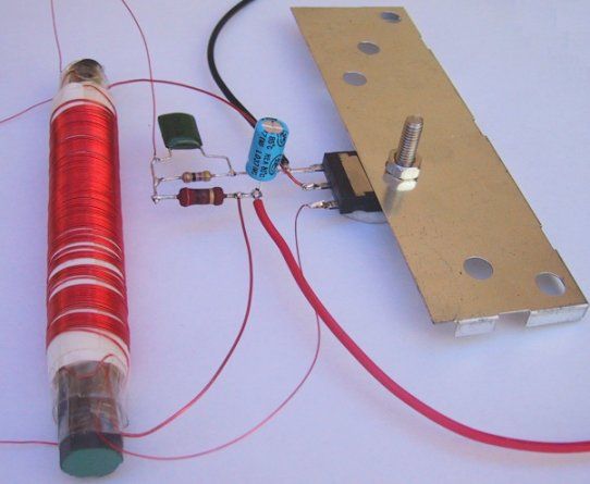
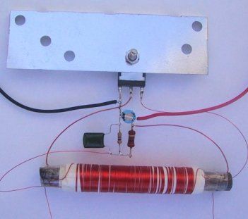
Two views of the 20 watt Fluoro
Inverter. The pre-built
pictures will help with construction. |

|
The 20 watt FLUORO CIRCUIT. |
The kit comes with PCB and adjustable brightness
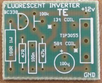
Fig: 2. The 240v AC fluorescent lamp
circuit.
THE 240v FLUORO
The 20-watt Fluorescent inverter
Kit. PARTS LIST Extras:
WINDING THE TRANSFORMER
The ferrite core of the transformer is an antenna rod from an old transistor
radio. You could use a slab antenna but we have chosen a 10mm diameter rod, 8cm
long and the first winding to be wound on it is called the primary.
This is a low-cost project for 20 or 40 watt fluorescent tubes. However the
most efficient is to use a 40 watt tube (or two 20 watt tubes in series). It's
a circuit you can put together from junk box components or build from a kit.
It's very simple to build and requires no printed circuit board.
The transformer is hand-wound on a ferrite rod (from an old transistor radio)
and the winding wire can be salvaged from an old transformer.
We are purposely keeping costs down to show how cheaply it can be put together.
Depending on your stock of parts, the cost could range from $3.00 to about
$15.00 and if the wires from the transformer are soldered to the ends of the tube(s), you can create a free-standing light that can be set-up in the garden
to illuminate a dark area without the fear of running 240v wiring. The cost of
powering the circuit is about 22 watts and this will produce the same light
output as a 60 watt globe.
With a normal fluoro operating on the 240v mains, a ballast (or choke) is
needed in series with the tube to limit the current after the tube has
"struck". This ballast dissipates about 10-20 watts for a 20 watt tube and
reduces the efficiency of the circuit.
If the ballast is replaced with an electronic circuit and high-frequency
transformer, the losses are less than 5 watts. Furthermore, if we do not drive
the tube as hard as the 240v version we can get even better efficiency.
The size of tube, you will need, will depend on the area you wish to illuminate
and the battery capacity you have available, however it is important to realise
that the higher wattage tubes offer the greatest efficiency.
This is because they have a longer
length and larger diameter (than say an 8 watt tube) and give more light over a
larger area. That's why we have concentrated our design on the 40 watt tube.
You can get plenty of circuits and devices that power the 4, 6 and 8 watt tubes
but nothing has been done for the 40 watt variety.
There is another range of tubes, commonly called the "compact fluoro" or high
efficiency fluoro. These are a folded fluorescent tube having a rating of either
11 watts, 13watts or 18watts. They are not covered in this project as they
are expensive to boy and more difficult to
drive. They are actually driven VERY HARD and if you feel one after it has been
turned on for a few minutes you will find the tube is quite warm.
They are not really suitable for indoor use as they take a while to come on and
don't give enough illumination for an average room. We have tried the whole
range of these tubes and come to the conclusion that they are only suitable for
outdoor use as a decorative lamp or for partially illuminating a dark area.
This is one of those situations where the old-style product is the best. I
think you will find that the glitter of the compact lamp has almost faded by
now as the public has come to realise they are not the whiz bang invention of
the century and have not taken over any of the areas already serviced by the
tungsten lamp or standard fluoro.
After all, you can buy a 100watt globe for less than $1.00 and a compact lamp
costs about $20.00. It will take more than 5 years for the savings in
electricity to equal the cheap 100 watt globe.
The one problem that lets compact lamps down is the electronic circuitry. The electrolytics in the base are driven very hard and tend to dry out after a few
years. We have found lots of discarded bases (with tube) with this problem.
Apart from this, the fluorescent lamp has a number of advantages over
incandescent lighting. The main one is efficiency.
This is due to the fact that it's a cold light, in comparison to incandescent
light where the light is produced by the heating of a piece of wire.
The other advantage is the light does not come from a point source and thus it
is more-evenly spread over a larger area.
Fluorescent lighting is approximately 400% more efficient than incandescent
lighting (50 Lumens/watt compared to 12 Lumens/watt for a 100 watt tungsten
lamp), although there are some losses in the ballast. A 20 watt tube (plus
10-20 watts for the ballast) gives the same light output as a 100 watt lamp,
when it is heavily driven in the 240v mode.
For a normal household, the lighting component of the electricity bill is only
a fraction of the total and doesn't warrant a house to be converted to
fluorescent lighting.
But if you are considering setting up a home in a remote area, where mains
electricity is not available, you will appreciate the advantage of
high-efficiency lighting.
With modern electronic circuits, fluorescent lamps can be designed to operate
very efficiently and with this project you can build the circuit yourself and
operate it from a 12v supply.
THE 12V SUPPLY
In any low-voltage situation the greatest component of consumption is lighting.
This is because all the other appliances have been converted to some other form
of energy. The fridge has been converted to gas. the toaster has been thrown
out, the jug has been changed to a saucepan or kettle on a fuel stove and the
electric fry pan has been forgotten.
All that has been left is the lighting and a few small appliances such as the
washing machine, portable TV and drill (12v rechargeable type).
When considering the sort of lighting you need, you must take into account the
type of work you will be carrying out such as eating, reading, repairing etc.
For some of these, the light from a camp-fire will be sufficient while for
repair work you will need the highest level of illumination.
To provide the required level there are two choices. The standard 12v globe,
and the fluorescent tube.
I have not considered the use of gas lighting as they remove the oxygen from
the air, produce a lot of heat and are potentially very dangerous.
If you need to carry out fine, detailed work, you will need a standard 12v
globe or even a 50 watt halogen lamp.
However for general room illumination, a 20 watt fluorescent will be adequate.
Let's see how we can make a 20 watt inverter.
The project we will be describing is not designed to drive any of the compact
(or folded) fluorescent tubes as they are driven much harder than ordinary
tubes and get quite warm after only a few minutes of operation.
This heating represents wasted energy and in this project we are trying to save
as much energy as possible.
Folded tubes are also less efficient than ordinary straight tubes as they have
two or four tubes running beside each other and when they are illuminated, some
of the light from one tube will hit against the walls of the others and be
lost.
The folded tube is not suitable for indoor use. All the tubes I have bought
have been a failure. Some took a long time to come on - up to 10 seconds to
"strike."
The other disappointment is the weak output for the first 10 minutes or so.
They take about 10 minutes to "get going."
I have an 18 watt compact lamp in my room at the moment and cannot read the
pages I am preparing. It's another invention that has "missed the bus" -they
are just not quite good enough.
I am going to replace it with a 100 watt globe and come back.
While in the process of changing the globe, I compared the 18 watt compact
fluoro with our circuit driving two 20 watt tubes and found them to almost the
same. They are equivalent to a 60 or 75 watt clear globe and is perfectly ok
for general lighting in a room.
There is an enormous difference between the circuit for a fluoro operating on
240v AC and one that operates on 12v DC.
Basically the 240v circuit relies on heating the cathodes at the ends of the
tube so that a relatively low voltage will strike the tube. After this, the
filaments can be turned off and the gas will be remain conducting.
In the 12v arrangement, the output of the transformer must be sufficient to
strike a cold tube and keep it illuminated without heating the cathodes.
We have all seen fluoro's in the kitchen of almost every home, and thousands in
department stores. But little do we realise the complex engineering that has
gone into their design (a lot of trial and error) and how the three items of a
fluoro circuit work.
These three items are: a fluorescent tube, a starter and ballast.
Figure 2 shows the circuit for this. When a fluorescent is turned on, it
flickers a few times then comes on.
What happens is this: When the power is applied, the tube has a very high
resistance between its ends and the only path seen by the 240v mains is through
the ballast, the filament at one end of the tube, the starter and finally
through the filament at the other end of the tube.
The ballast is a single winding on an iron core and it has a number of
functions. Firstly it acts as a current limiting device so that when the
circuit is first turned on, the voltage across the starter is about 130v. The
starter consists of a glass tube with two electrodes. The 130v is the
characteristic voltage of the starter and is governed by the mixture of helium
and hydrogen in the tube.
When a voltage is applied to its terminals, the gas inside begins to glow and
heats up a bi-metallic strip (one of the electrodes) and it touches the other
electrode.
This shorts out the starter and turns off the glow. The ballast now provides a
voltage of about 8 - 12v for each filament and they begin to glow.
They are only designed to glow to a dull red and this begins to heat up the gas
in the fluorescent tube ready for the next part of the cycle.
After a second or two, the bimetallic strip in the starter cools and breaks
contact. This causes the current in the ballast to reduce suddenly and a
voltage of 800v to 1,000v is produced across its winding.
This voltage is passed to the ends of the tube. Since the gas at the ends of
the tube has already been heated by the filaments, the 1,000v is sufficient to
strike the rest of the gas along the length of the tube. Once this occurs,
current starts to flow and a voltage of about 110v appears across the tube.
This voltage is again governed by the characteristics of the ballast and is not
enough to restart the glow in the starter. If the tube does not strike on the
first occasion, the starter glows again and this is where the flickering comes
from.
The final function of the ballast is to limit the current so that the
tube consumes its rated wattage. If a tube that has been "struck" is placed
directly across the mains, a very high current will flow and it would blow up
as the resistance between the ends is very low.
It is classified as having "negative resistance" as the flow of current causes
the impedance of the tube to decrease.
20 WATT FLUORO
The wattage of a fluorescent tube is a characteristic of its size and vice
versa; the wattage determines the size. That's why a 20 watt tube is 2 feet
long and a 40 watt tube is 4 feet long.
The design of a tube is a complex mathematical equation (a lot of
experimentation has gone into its design).
The tubes are filled with a gaseous mixture that produces ultra-violet light
when operating and this light hits against the walls of the tube to excite the
coating on the inside to produce visible light.
The gas and the coating are all poisonous and the emission of the ultraviolet
waveform from an uncoated tube is quite dangerous to the eyes, so experimenting
with tubes other than operating them as per this project is to be avoided.
You can buy uncoated tubes (called ultraviolet tubes) for lighting effects,
EPROM erasing, special heating, and germicidal applications. Do not use any of
these tubes in this project as the voltage we are producing will create
different effects and damage your eyes.
12v INVERTER
Now for the 12v version.
The circuit doesn't require many components but its operation is quite complex.
The clever component is the transformer. It performs 3 functions.
Firstly it is acting as a feedback component for the transistor to create an
oscillator circuit. Secondly it is providing a high voltage (over 1 000 volts)
to strike the tube and keep it struck and thirdly it is supplying spikes of
energy to illuminate the tube.
The circuit is shown in figure 1 and we will take a detailed look at how the
transformer carries out the three functions.
The transformer in this project is not a lethal device as the output wattage is
slightly below the value that produces electrocution. However the output is in
excess of 1,000v and the ends of the secondary winding should not be touched
when the transformer is operating.
To get a shock you must touch both
ends at the same time - it is not sufficient to touch one end and any other
part of the circuit as the secondary is an isolated winding.
Even a simple transformer such as the one we are winding in this project will
demonstrate a number of interesting features. One of them is the ability to
step-up a voltage. This is the main purpose in this project as we require a
voltage of approximately 1,000v to strike the tube.
Another interesting feature is the availability to get positive or negative
voltage (phase) from a separate winding on the transformer, simply by
connecting the winding around one way or the other. In this project we connect
the winding to get positive feedback so that a single transistor will drive the
circuit.
HOW THE OSCILLATOR WORKS
The oscillator works on positive feedback. This positive feedback comes from a
separate 13 turn winding on the transformer called the feedback winding.
The cycle starts by turning on the transistor a fair bit via the 180R resistor
on the base and this causes current to flow in the primary winding. The flow of
current causes magnetic flux to be produced by the winding and this passes
through the ferrite core. The feedback winding is also wound around the core
and the magnetic lines pass through this winding and produce a voltage.
The winding is connected to the transistor so that the voltage from the winding
ASSISTS the voltage from the 180R resistor and causes the transistor to turn
on harder.
Thus more current flows through the primary winding and the magnetic flux
increases. This causes more voltage to be produced in the feedback winding and
the transistor turns on even harder.
This continues until the transistor is fully turned ON and maximum current is
flowing in the primary winding.
Now comes the important part.
Even though maximum current is flowing in the primary winding and maximum flux
is produced in the core, this flux is a steady flux and not an increasing flux.
The only time a voltage is produced in a secondary (or feedback) winding is
when the flux is INCREASING (or decreasing). When the flux is stationary, the
voltage in any of these windings ceases to be produced.
Thus we come to a point in the cycle where the current in the primary is a
maximum but the voltage in the feedback winding is zero.
The only current flowing into the base of the transistor comes from the turn on
resistor but this is note enough to fully turn the transistor ON and so the
transistor turns off a small amount.
This has the effect of reducing the flux in the ferrite rod and we now have a
situation where the flux is DECREASING. This changes the situation in the
feedback winding. The voltage in the feedback winding is now produced in the
OPPOSITE DIRECTION and the transistor begins to turn off even more.
The magnetic flux begins to collapse very quickly and this produces a very high
reverse voltage on the base of the transistor (up to about 25v) to turn the
transistor off completely.
This is how we get a positive and negative voltage for the transistor.
This is quite an amazing achievement as the voltage through the primary doesn't
change direction - it merely increases and decreases in value - but the voltage
from any of the other windings changes direction!
The collapsing magnetic flux cuts the turns of the secondary winding and
produces a voltage of about 2.5v per turn in the 450 turns, making a total of
about 1 ,000 appearing across the ends of the tube. This is sufficient to
strike the tube and as we mentioned above, the resistance (or impedance) of the
tube reduces as more current flows. In our case the voltage across the tube is
about 400v (this voltage depends on how hard the tube is driven and is riot a
fixed value).
When the magnetic flux has almost fully been converted to electrical energy,
the 180R turn-on resistor on the base of the transistor starts the cycle over
again.
The voltages produced by the transformer are very spiky and the gas in a
fluorescent tube is very quick to react to these spikes. The gas produces
ultraviolet light that strikes the fluorescent material on the inside of the
tube and causes it to produce visible light.
The tube forms part of the load for the transformer and has an effect on
quenching the spikes to the transistor so it is not advisable to operate the
transformer without the tube connected.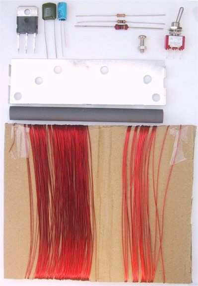
1 – 2R2 1/4watt (for testing)
1 - 47R 1/4watt
1 - 180R 1watt
1 - 47k
1 - 100k mini rim pot
1 - 100ngreencap
1 - 100u 16v electrolytic
1 - BC338 transistor
1 - TIP 3055 transistor
1 - on/off switch
1 - 12mm bolt and nut for transistor
1 - heat-sink 5cm x 10cm
1 - ferrite rod 10mm dia x 8m long
1 - 30m winding wire .28mm dia
1 - 4m winding wire .61 mm dia
(wire diameters are NOT critical)
1 - insulation tape either sticky tape
or masking tape
1 - interlayer insulation - paper
2 - 20 watt fluorescent tubes
1 - box to house project
1 - 6m of figure-8 flex to go between inverter and tube(s)![]()
This consists of 58 turns of wire spaced slightly apart so that is occupies the
centre 6cm of the rod. The first thing to do is wind two layers of insulation
around the rod so that the wire does not touch the rod and create a short.
Leave the first 8 - 10cm of wire and start winding with the thick .61mm wire.
But firstly hold the end of the wire in place with a short piece of sticky tape
folded over itself and stuck along the length of the rod, where the winding is
to be placed. Continue winding and fix the other end in a similar manner,
leaving 8 - 10 cm for connecting to the rest of the components.
Place one layer of paper over this winding and secure both the start and end of
the paper with sticky tape. Make sure this insulating paper is tight by rolling
it like a cigarette before sticky-taping.
The next layer is called the feedback winding and consists of 13 turns of the
thin .28mm wire, wound in a spiral fashion so that it takes up the full length
of the 6cm.
Terminate both the start and finish of the winding with sticky tape to prevent
it unwinding. Cover this with a layer of insulation.
Now, for the final winding, called the secondary.
This consists of 450 turns of .28mm wire, wound in 3 layers of 150 turns.
The winding does not have to be neat and you could quite easily jumble-wind the
turns and it would work perfectly ok, however there are two factors to
remember.
The voltage between the start and finish of this winding will be about 1,000
volts and the insulation on the wire is only about 100v. So the start and the
finish must not be near each other. This also applies to most of the other
turns so the best way to prevent the inner-turn sorts is to carefully wind the
turns side-by side.
This also produces the best results.
Leave 8 - 10 cm of wire and hold the start in place with a piece of sticky-tape
folded over itself and stuck to the insulation. Wind 150 turns neatly across
the 6cm of the transformer and hold the last turn in place with sticky tape
before placing a layer of insulation over the winding. Continue with the next
layer and one more, making a total of 450 turns.
Cover the last layer with insulation, tin the ends of each of the windings with
a hot soldering iron and plenty of solder and the transformer is complete.
|
20 watt FLUORO INVERTER LAYOUT. |
MAKING THE CIRCUIT
The circuit is constructed on and around the leads of the transistor. Refer to
the diagram to see how this is done
CONNECTING THE
TRANSFORMER
The transformer has 6 wires.
The two high voltage wires from the secondary can be connected around either
way to the tubes.
Either lead of the primary, can be connected to the collector, and the other
end connects to the positive of the battery and 180R resistor. Now comes the
difficult part.
The feedback winding must be connected to the base and the join of the
resistors so that the transistor gets positive feedback. You can do this by
marking the start of the primary winding and the start of the feedback winding
and connecting them in a particular way, but if you are wrong, a very high
current will flow and the transistor will be damaged. We have devised a
fail-safe method that doesn't rely on you having to remember which is the start
of each of the windings, or the direction of the winding. It's called trial and
error with safety resistor.
Place the 2R2 safety resistor in the positive line as shown in the circuit
diagram and connect the feedback winding any way you wish. Turn the project ON
AND OFF very quickly. If the fluoro's don't come on immediately, the feedback
winding is around the wrong way. The safety resistor will only allow 5amps to
flow thorough the circuit and the transistor will not be damaged.
When the fluoro's come on, remove the 2R2 and the project is ready to use. Use the
figure-8 flex and hang the tubes in your bush shack or workshop.
See the project used in a farm application.
email from a reader:
I made the
transformer by covering the ferrite rod with a
layer of heatshrink tubing before winding and a layer of
insulation tape rather than paper between windings. I covered the whole
thing, once wound, with a final layer of insulation tape to hold
everything in place, though if I'd had a suitably large piece of
heatshrink I would have used that. This method of winding worked very
well
and the transformer is not too bulky. I wound it very neatly with the
windings as evenly distributed over the length of the rod. I'm not sure
how the tape would affect efficiency but the end result seems to work
well.
For first switch-on I used the 2R2 limiting resistor as recommended and
this worked well, though readers should be aware that the advice to
'turn
the inverter On then Off straight away' should be followed, unless they
wish to 'smoke' the resistor. On my setup the resistor started smoking
almost immediately, though I still wasn't sure whether the feedback
winding was around the right way because I had just one tube
of the pair lighting up. As nothing
about this was mentioned, I
was puzzled.
Current draw was not excessive, (no doubt due to the resistor),
but the transistor got very warm quite quickly, even with the heatsink
I used (a heavy-ish PCB mounting model).
Perhaps I had one dud tube and it was working OK, the tranny getting
warm
because of the spikes affecting it. However, swapping the
feedback coil got things humming along, with both tubes at full
brightness
and at 2 amps current draw at 12 volts (according to my power supply
meter, which may not be too accurate). After 10 minutes of running, the
transistor was only just getting warm; with a slightly larger/more
efficient heatsink it would run all day long if necessary.
It threw me for a few minutes having only one tube light up on first
use;
(albeit at lower-than-usual brightness, but having not seen these tubes
going before I wasn't sure how bright they would get). It made sense
that
the feedback coil was the wrong way around, but readers might like to
know
one tube may light up, even with it wired backwards, though of course
the
tranny getting very hot is a give-away as well.
I used two Mirabella FL15T8, 15 Watt, 410 mm tubes.
Dave Thompson
![]()