
Click for Shape Memory Applications Inc
Suppliers of Nitinol
Page 2
P1 P3
PROPERTIES OF NITINOL
by John Iovine
Nitinol is an alloy of nickel and titanium that
belongs to a class of materials called SHAPED MEMORY ALLOYS (SMA). SMA's
have interesting mechanical properties. Nitinol for example contracts when
heated, which is the opposite to standard metals, which expand when heated.
Not only does the alloy contract, but also it produces 100 times greater
thermal movement (expansion, contraction) than standard metals.
Another interesting property of SMA's is the
shaped memory effect (SME). The alloy can be heat-treated to remember a
particular shape. Afterwards, if the shape is bent and distorted, the alloy may
be heated to regain its original shape. The SME property is used in a few
toys like the Livewire toy. According to the directions, it is bent into
an irregular shape, placed in hot water and the wire pops back into shape.
The Livewire toy is made of nitinol wire
with a low transition temperature (the temperature of hot water).
The History of Nitinol
Although people have known about and experimented
with SMAs since 1932, it wasn't until 1961 that they came out of the
laboratory. William Beuhler, working at the US Naval labs, discovered the SME
effect in an alloy of nickel and titanium. At the time the scientific
team were trying to develop a heat and corrosive resistant alloy. What they
discovered was a relatively inexpensive and safer (non-toxic) SMA.
The team named the new alloy Nitinol
(pronounced night-in-all). The name represents its elemental components and
place of origin. The "Ni" and "Ti" are the atomic symbols
for nickel and titanium. The "NOL" stands for the Naval Ordinance
Laboratory where it was discovered.
The mixture of nickel to titanium in nitinol is
about equal. The smallest change in the ratio of the two compounds has a
dramatic effect on the transition temperature of the resulting alloy. For
instances, a 1-2% difference in the ratio varies the transition temperature from
–100°C to +100°C. Every company manufacturing nitinol products must hold
the ratio of the components to a precise level to insure a stable and
repeatable transition temperature. The nitinol alloy we are experimenting with
has a transition temperature of 70°C.
How It Works
The properties of nitinol rely on its dynamic
crystalline structure. The molecular structure is sensitive to external stress
and temperature. The alloy has three defined temperature phases.
1. Austenite Phase. Temperature is above
transition temperature. The transition temperature varies depending upon the
exact composition of the nitinol alloy; commercial alloys usually have
transitional temperatures between 70°C to 130°C (158°F to 266°F). The yield strength
with which the material tries to return to its original shape is considerable;
35,000 to 70,000 psi. Crystalline structure is cubic. 2. Martensitic Phase. Low temperature
phase. The crystal structure is needle-like and collected in small domains.
Within the small domains the needle-like crystals are aligned. The alloy may be
bent or formed easily. Deformation pressure is 10,000 to 20,000 psi. Bending
transforms the crystalline structure of the alloy producing an internal stress.
3. Annealing Phase. High temperature phase.
The alloy will reorient its (cubic) crystalline structure to
"remember" its present shape. The annealing phase for the nitinol
wire we are working with is
540°C.
Physical Properties
| Tensile Strength | 200,000 psi |
| Melting Point | 1,250°C (2,282°F) |
| Resistance | 1.25 ohms per inch (.006 wire) |
| Corrosion Resistant |
When nitinol is at room temperature it is in the martensitic phase. When the alloy is bent, the needle-like crystalline structure within the domains deforms, creating internal stress. When the alloy is heated above its transitional temperature (Austenite phase), the crystalline structure changes from needle-like to cubic. The cubic structure of the alloy doesn't fit into the same space as the needle-like domain structures formed when the alloy was bent. The alloy relieves the stress by returning to its "remembered" crystalline cubic shape. If the alloy hasn't any been deformed or stressed, the crystalline structure changes still occur, but it doesn't result in any net movement.
Nitinol Wire
Nitinol generates a shape resuming force of 22,000 pound per square inch. In our experiments we will work with either 6-mil (.006 inch diameter) or 15-mil (.015 inch diameter) wire. The 6-mil wire has a contractive force of 11 ounces; the 15-mil wire has a contractive force of 63 ounces (4 lbs). The wire can contract up to 8%-10% of its length. For longer lifetime (greater than 1,000,000 cycles), the contractions should be restricted to only 6% of its length. Contraction and relaxation depend solely on the temperature of the nitinol alloy wire. Any method of heating and cooling may be used. An easy way to heat the wire and one that is commonly employed is passing an electric current through it. Nitinol wire has a high resistance, approximately 1.25 ohms per inch for the 6-mil wire. The resistance of the wire to the electric current generates sufficient heat (ohmic heating) to bring the wire through its transition temperature. Nitinol wire usually has a counter-force applied to it in the opposite direction of its contraction. The counter force resets, or stretches the wire back to its original length when in the low temperature phase. This is called the bias force.
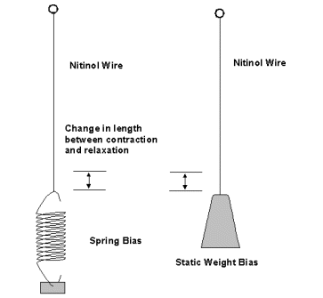
If the nitinol wire is brought to its transition temperature without a bias force it will contract, however, when it cools it will not return to its original length. Consequently, without a bias force, when the wire is reheated no further contraction will take place. In most applications a bias force is applied to the wire constantly. Figure 2 illustrates two methods of applying a bias force, a spring and a static weight. The speed and strength of the wire contraction depend upon how fast and how high the temperature of the wire is increased. For example, 400mA of electrical current through the 6-mil nitinol wire will produce a maximum pull of 11 ounces and full contraction in one second.
Reaction time can be faster, in the millisecond range. To achieve this high current short duration pulses are used. When doing this consideration must be given to the mass and speed of the material to move. The faster you move a given mass the greater the inertia that must be overcome. If the inertia becomes greater than 6 lbs. for the 6-mil wire, it will snap.
Full contractive force is produced at the beginning of a cycle. In contrast to standard electrical solenoids that develop full strength near the end of their cycle.
Activating Nitinol Wire As mentioned, nitinol wire may be heated by simply passing an electrical current through the wire. The resistance heats the wire and it contracts. The volume of the wire doesn't change during contraction. As the wire decreases in length, its diameter increases by a proportional amount, keeping the volume of the wire constant. The activation temperature of the wire is 70°C or 158°F.
Direct Electrical Heating
Nitinol wire can be activated using a low voltage DC (6 - 12volts) power supply. A simple circuit can be constructed using a battery, switch and a small length of nitinol wire (see figure 4). When activating a wire using DC current it is important not to overheat the wire, or its properties will degrade. DC current doesn't heat the wire evenly. A better method is to heat the wire using pulse width modulation.

A Simple Nitinol
Demonstration
The machine screws, nuts and expansion spring
may be purchased at a local hardware store. To make the device, drill two
holes in the wood on opposite ends to accommodate the machine screws as shown.
The screw and nuts between the two end screws is not secured to the wood, but
is free standing. The nitinol wire is connected to the left screw (see detail
in figure 5). The spring is looped around the right end
screw. The free standing machine screw and nuts connects the nitinol wire and
spring together.
Figure 5 is a simple
mechanical demonstration to display the properties of the nitinol wire alloy.
It is basically an electric muscle that flexes. The materials you need are
three machine screws (6-32 x 2" length) with nine nuts, a piece of wood or
plastic approximately 12" long, a small expansion spring (approx.
2-3" length) and of course a length of nitinol wire.
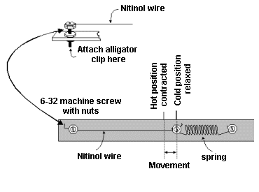
Keep in mind the 6-mil nitinol wire has a pull
of about 11 oz., so don't stretch the spring so far that the tension is so
great the nitinol wire isn't able to contract. At the same time it should be
tight enough for it to take the slack of the nitinol wire when it is relaxed.
To make the connections from the DC power
supply to the demonstration, use small alligator clip jumper wires connect to
the back of the two end screws. The machine screws as well as the spring are
electrically conductive, allowing current to flow to the nitinol wire.
When you switch on the current to the nitinol
wire demonstration unit, the wire heats up quickly, contracts and pulls the
freestanding machine screw closer to the right side. If you mark the starting
position of the freestanding machine screw, you can accurately measure the
contraction of the wire. When power is removed the wire cools, allowing the
spring to elongate the nitinol wire and return to its initial position.
Since we are using a DC power supply, only
connect the power momentarily. It's too easy to over heat the wire and degrade
the nitinol properties. On the next page, we will improve upon this
system.
On the previous page, we activated nitinol wire using a basic DC current. While this works, it is easy to overheat and potentially damage the nitinol wire. This month we will construct a pulse width modulation (PWM) circuit. Activating nitinol wire using pulse width modulation has distinct advantages. The oscillating on-off of the power allows for more even heating of the wire (reduces hot spots). The duty cycle of the square wave can be varied to generate a degree of proportional control over the contraction. These factors allow us to activate the nitinol wire with better control for longer periods of time without causing heat damage to the crystalline structure of the nitinol alloy.
The PWM circuit is made from a 555 timer, (see figure 6). By using two transistors Q1 and Q2 and potentiometer with the 555 timer we can create an output with a relative constant frequency with a variable duty cycle.
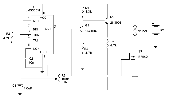
When the output from the timer (pin 3) goes
high, both transistors Q1 and Q2 turn on. The current through Q1, R3 and
portion of the Potentiometer (R4) designated RA charges the timing capacitor
C1. When the voltage on C1 reaches 2/3 Vcc, the output on the 555 timer (pin 3)
goes low.
At this point both transistors Q1 and Q2 turn
off. Capacitor C1 begins to discharge through the portion of the potentiometer
(R4) designated as RB and R5 via pin 7 (Discharge pin) of the 555 timer. When
the voltage on C1 drops to 1/3 Vcc the output switches high and the timing
cycle repeats.
The duty cycle of the square wave output can be
changed by varying the resistance of the potentiometer.
The output of the 555 timer (pin 3) connects to
a MOSFET transistor that switches the current on and off to the nitinol wire.
If the current from the PWM circuit is too powerful to control the nitinol wire
proportionally, place an 8-ohm (2 watt or greater) resistor in series with the
nitinol wire to reduce power.
Superelasticity
Superelasticity is a unique property of SMA. If
the SMA is deformed at a temperature slightly above its transition temperature,
it springs right back into shape. This springy property is called
superelasticity. Manufacturers have capitalized on this property finding useful
medical and dental applications.
For instance, low temperature nitinol wire is
used as orthodontic arch-wires in braces. The nitinol wire provides a low
constant force at human body temperature used to straighten teeth while
reducing the need for wire retightening. The transition temperature of these
wires are made so that they generate force at the temperature of the human
mouth (about 37°C) (98.6°F).
Supereleastic nitinol tubing are used as
surgical catheters. The nitinol catheters can be bent more often than
their steel counterparts allowing surgeons to access difficult areas of the
human body.
Directional Digit
This project uses nitinol wire to create a
directional digit. Using three or four direction digits in a circle one can
create a basic robotic arm gripper. The digit consists of a 3-4 inches of a
resilient rubber or silicon tubing, 12 inches of nitinol wire, 12 inches of 22
Ga. insulated stranded wire, one 6-32 machine screw with two nuts, 8-32 machine
screw with two nuts and approximate 7 inches of a hard plastic tubing.
Take the length of rubber tubing and cut four
or five louvers on one side (see figure 7). You can cut the
louvers using a scissors or wire cutter. The louvers force the rubber tubing to
collapse to one side (directional) when compressed. Next take the 6-32 machine
screw and nuts. Position one end of the nitinol wire under the screw head and
tighten one nut up against it. Then remove 1/2 inch of insulation from the 22
Ga. wire, wrap the portion of un-insulated 22 Ga. wire around the 6-32 screw
under the first nut. Tighten up the second nut against the 22 Ga. wire.
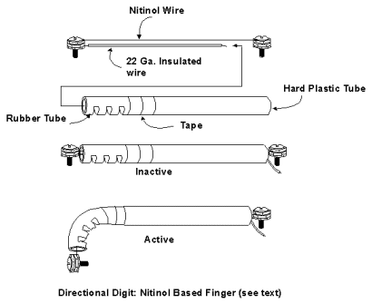
Thread the open ends of the nitinol wire and 22
Ga. wire through the rubber tubing and then through the hard plastic tubing.
The 6-32 nut holding the 22 Ga. wire and nitinol wire should be flush with the
top of the rubber tubing. Secure the base of the rubber tubing to the top of
hard plastic tubing with tape (masking, scotch or electrical).
Attach the free end of the nitinol wire to the
8-32 machine screw and nut in a similar manner as described before. The 8-32
machine screw and nitinol wire assembly must be positioned at the base of the
hard plastic tubing, without any free space in-between. You may have to
collapse the upper rubber tubing while attaching the 8-32 machine screw to get
it position correctly.
Attach the PWM
circuit to the nitinol wire (via the 8-32 machine screw) and the free end
of the 22 Ga. wire. By rotating the potentiometer you will be able to bend the
the upper rubber tube portion digit. The digit will bend in the direction of
the louvers. Reducing the power allows the digit to straighten out.
If you place three or four of these digits in a
circle, with the louvers pointed toward the center, you will have a rudimentary
gripper.
Heat Engines
If you thought that nitinol material would make an
excellent material to construct heat engines you are not alone. Over the years
a number of experimenters and companies have created nitinol heat engines. A
patent search on the Internet using the key words nitinol and engine turned up
several heat engine designs. Most of the patented designs are mechanically
complex and don't lend themselves easily for quick experimentation. However,
there is a simple heat engine design that found its way into a few toys. Let's
take a quick look at this design.
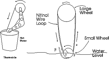
 Thermobile
The Thermobile (see figure 8), uses a loop of
nitinol wire to generate power. The nitinol loop is placed on two free rotating
wheels, This device uses only hot water (hot side) and cool ambient air (cool
side). The smaller brass wheel of the Thermobile is immersed in a hot liquid.
In the Thermobile the nitinol loop wire has
been trained to remember a straight shape. When the loop travels into the
hot water it is brought above its transition temperature and attempts to
straighten out. Look at figure 9, at position 1 the nitinol
wire is relatively straight and cool. As the wire moves from position 1 to 2,
it is bent around the small brass wheel and enters the hot water. As the wire
moves from position 2 to 3, the hot water brings the nitinol wire above its
transition temperature and it tries to straighten out. When attempting to
straighten out the nitinol wire takes a form depicted by the dotted lines. In
doing so, the wire generates a tugging force, F, along the loop. As the wire
segment moves from position 3 to 4 it straightens out. As the wire
travels from position 4 to position 1, through the air and around the large
wheel it has sufficient time to cool below its transition temperature and is
ready for another cycle.
In short, the temperature differential causes
one side of the loop to stiffen (hot water side) while on the air side of the
loop the nitinol cools and relaxes. A mechanical force is produced that causes
the wheel pulleys to rotate.
In some cases it is necessary to jump start the
engine by rotating the larger wheel. Interestingly, the Thermobile hasn't a set
rotational direction. Whichever way it is started it will continue to rotate.
The Thermobile can also be solar powered. A magnifying lens focusing sunlight
on the brass wheel also supplies sufficient heat to power the engine.
Larger Thermobile engines have been built and
tested using nitinol loops. One engine built by Innovative Technologies
International (ITI) in 1982, contained 30 nitinol wire loops. The nitinol wire
used in the loops was 22 mils in diameter. The engine was tested using a hot
water bath set at 55°C and an air temperature of 25°C. The engine reached a
speed of 270 RPM and continued to operate for 1.5 years without failure. The
nitinol wire had undergone 2.1x10⁸ cycles without any breakage or observable
degradation in performance.
For a University experiment on the Thermobile,
click HERE.
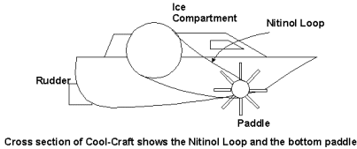
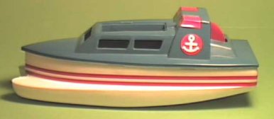 The
Cool-Craft boat (see figure 10) also uses a loop of nitinol wire to
power a small plastic boat. The nitinol loop is place on two free rotating
wheels, see approximate cross section of Cool-Craft boat in figure
11. The smaller bottom wheel has paddles that move the boat when it
rotates. The boat is made with a small ice compartment on top. The top ice
compartment chills one side of the nitinol loop. The other side of the nitinol
loop travels through warm water where the toy boat is placed. The heat
differential between the warm water and ice is enough to activate the nitinol
wire loop and power the craft.
The
Cool-Craft boat (see figure 10) also uses a loop of nitinol wire to
power a small plastic boat. The nitinol loop is place on two free rotating
wheels, see approximate cross section of Cool-Craft boat in figure
11. The smaller bottom wheel has paddles that move the boat when it
rotates. The boat is made with a small ice compartment on top. The top ice
compartment chills one side of the nitinol loop. The other side of the nitinol
loop travels through warm water where the toy boat is placed. The heat
differential between the warm water and ice is enough to activate the nitinol
wire loop and power the craft.
This is fertile field for experimentation. I
have seen a number of heat engine designs that use rubber bands. A few of these
designs look as thought they would lend themselves to incorporate nitinol wire
in place of the rubber.
- Flexinol wires contract by 3-5% irrespective of gauge size
- Flexinol Wires is rated at >1,000,000 cycles when used as per manufacturer's instructions
- Flexinol Wires contract very rapidly - as fast as you can heat them.
- Wires relax more slowly - it is dependent on ambient cooling conditions
- Wires must be pulled back to their original, relaxed condition by external means (eg spring, gravity, rubber band!)
- Flexinol wire is available in 2 transition temperatures - 70°C and 90°C
- The higher the transition temperature, the faster the relaxation and the more power is required to heat them.
- Flexinol Wires are available in 5 gauges: 50um, 100um, 150um, 250um, and 370um.
- Contraction forces are typically: 35gmf, 150gmf, 330gmf, 930gmf and 2000gmf
- Relaxation forces required: 8gmf, 28gmf, 62gmf, 172gmf, and 380gmf
- Cycle rates are typically 9-40 cycles/minute( for the 50um wire) 70°C wire (LT grade) and 13-65 cycles/min for the 90°C wire (HT grade)
- Typical Operating Currents; 50mA, 180mA, 400mA, 1000mA and 2500mA
- All wires require typically 0.3V/cm length.