P6
THE PIEZO DIAPHRAGM
A piezo diaphragm is not an active device. It does not produce a sound when DC
is applied. It requires an AC signal.
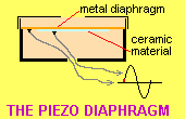
When voltage is applied so that one electrode is positive and the other negative,
the ceramic material increases in size. Since it is glued to the side of the
metal disc, it causes the disc to bend or "dish." When the voltage
is removed, the plate returns to its flat condition.
The animation above shows the piezo diaphragm in a
housing. This housing makes the diaphragm robust and improves its output.
INTRO
The "piezo" is everywhere.
Its uses are endless, from musical cards, watch alarms, tone producers for dialling phone numbers, to
alarms, glass-break detectors and sirens and although it appears
to be very simple, its principle of operation is quite complex.
The secret is piezo-electric material glued to the diaphragm.
This material increases and decreases in size when a voltage is applied
to it and this causes the metal diaphragm to bend like a saucer.
Up to now we have seen piezo-electric crystals in record players,
gas lighters and other devices where the crystal is bent or struck
and it produces a voltage. But in the piezo diaphragm, it works in
reverse. A voltage is applied to it and the crystal changes in shape.
The manufacture of a piezo diaphragm is quite complex. Depending on
the quality of manufacture, the result can be quite sensitive or insensitive.
"Hobby" piezos are mostly junk and have very poor output. Quality
devices are available from recognised wholesalers and are far superior.
But unless you know how to test them, you will not be able to pick
the good from the bad.
The word "piezo" is used for a whole family of piezos and this is
where the confusion comes in. One type of piezo is simply an element
or diaphragm and requires an external driving circuit for it to emit
a sound. The other has the drive circuit incorporated in the case,
along with the piezo diaphragm, and this allows it to produce a tone,
beep or chirp, (according to the complexity of the electronic circuit
driving it) simply by connecting it to a DC supply.
There isn't an easy way of telling one from the other, if you can't
see inside the case, so you have to know what to do. This article will
help.
TYPES OF
PIEZO
The piezo is sometimes called: "piezo," "buzzer," "piezo buzzer,"
"piezo tweeter" or "piezo
siren."
They are not all the same type of device.
There are two groups.
One consists of a piezo diaphragm with built-in circuitry to activate the diaphragm to
produce a sound or tone when a DC voltage is applied.
The other consists of ONLY a diaphragm and requires an AC waveform or pulsed-DC to
produce a sound. This is the type of piezo we will be describing.
It is called a PIEZO DIAPHRAGM. The symbol for a PIEZO DIAPHRAGM
is shown below:
![]()
It has infinite resistance but is seen by a circuit as a
capacitor of
about 22n (10n to 60n depending on size). When a signal is delivered at
the operating frequency it
is seen by the circuit as an IMPEDANCE of about 500 ohms.
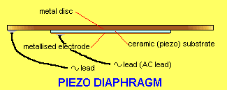
The piezo consists of a thin brass plate with a thin layer of ceramic material glued
on one side. On the other side of the ceramic is a very thin layer of metal to create
the top plate (called an electrode). The brass diaphragm forms the other terminal.
This is shown in the diagram below:
If the voltage is now applied in the opposite direction, the plate
"dishes" in the opposite direction.
If this process is
repeated at a vary fast rate, the plate produces a characteristic sound.
If the voltage is increased, the "dishing is greater and thus the sound intensity increases.
If the frequency of the signal (the voltage) is altered, the resulting frequency produced
by the piezo is altered.
By holding the outside of the diaphragm rigid and enclosing
it in a resonant chamber, the sound is mechanically amplified and
the result is very impressive - although very annoying!
We are all familiar with the beeps and tunes that piezos produce
from watches and musical cards and although they sound very "tinny,"
we have to live with the fact that they are very efficient producers
of sound.
The output from a piezo depends on the applied voltage and also the
quality of the piezo substrate. This substrate is polarised (not polarised
according to positive and negative voltage but according to direction
of expansion and contraction) and the degree of polarisation determines
the amount of movement for the voltage applied.
It must be remembered that a piezo element is a passive device and
cannot produce a tone by itself. It requires a drive circuit from
a computer or a transistor oscillator for it to function.
Also, the quality (especially music or voice) is dependent on the
thickness of the diaphragm and piezo substrate.
The overall loudness depends on the applied voltage and the size of
the diaphragm.
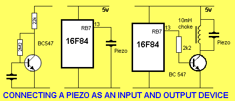
A piezo diaphragm can be used as an input or output
device. The diagrams below show how to connect it to a transistor as an input
device and to the output of a microcontroller, as an output device.
There are two modes of operation for the device.
2.
A "whistle" (commonly called AUDIO) can be delivered to the diaphragm and
an output will be produced.
If an AC voltage is applied to the device, (one lead is called the "reference lead"
or "earth lead" or "0v lead" and the other lead traces the
waveform shown above), the diaphragm will "dish" (move) as shown
in the animation. When the waveform goes "positive," the dish bends in one direction. When the waveform goes "negative," the diaphragm
bends in the other direction.
If a CRO is "hooked-up" to the two leads, it will display the
waveform shown above.
If the AC voltage is removed (the CRO remains connected), and a whistle
is applied through the hole in the top of the device, the
output will be as shown in the animation. As the metal diaphragm
moves in response to the whistle, the ceramic material will produce a voltage
(a waveform) as shown above.
RESONANT FREQUENCY
This frequency is determined by the size and
thickness of the diaphragm and also the quality of the substrate and
cannot be changed by the user.
Resonant values are obtained from the specification sheet that comes
with all good quality piezos. It is necessary to select the correct
value of inductance to get the maximum output for the frequency it is
operating at, and this is generally found from data sheets
or by trial and error.
3 LEADED PIEZOS
Most piezos have 2 leads, but some have 3. The third lead is
connected to an electrically isolated silvered terminal on the substrate
and it sees a small sample of the signal on the piezo. This lead is
called a feedback line and is connected to the input of an oscillator
to produce positive feedback to maintain frequency. This type of
diaphragm is usually placed in a package containing the "exciting"
(oscillating) circuitry. It is effectively equal to a small capacitor connected to one
of the plates. The diagram below shows a 3-leaded piezo. We will not
be covering this type of diaphragm.
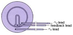
A 3-leaded piezo diaphragm
MAXIMUM VOLTAGE
All piezos have a maximum voltage that can be placed across the terminals
before the substrate breaks down.
The only way to see the driving voltage is to use a CRO. This is important when designing a new circuit
to make sure the voltage does not puncture the piezo-electric material.
BE CAREFUL
To get the maximum output from a piezo diaphragm it is necessary to
hold the outside rim firmly so that the brass diaphragm can deflect
in the centre.
An unrestrained diaphragm will have very little output and to increase
the output even more, it can be housed in a small case
to act as a sounding cavity.
Sometimes a driving circuit is present in the case and to find out
if this is so, it is necessary to connect the leads to a 6-12v DC supply. If a tone is generated, a driving circuit is present.
If only a click is heard, the case contains only a diaphragm.
It is essential to know exactly how the piezo device is structured so that the
appropriate drive circuit or drive voltage can be applied. If the
drive-circuit is internal, a DC voltage can be applied, provided the positive
and negative are connected to the correct terminals.
THE PIEZO DIAPHRAGM AS AN INPUT DEVICE
The piezo diaphragm can be used as an input device. It has some advantage
over an electret microphone and some disadvantages.
The piezo diaphragm is not as sensitive as an electret mic and the output is
harsh and metallic. In other words, the output is not as high as an electret
mic when detecting low-level sounds. It is not suitable for reproducing
quality audio as the sound is not very clear.
However it can be used to pick up sounds, especially the breaking of glass
(glass-break detector) or other loud sounds, to turn on a piece of equipment.
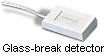 A glass-break detector sells for $10 to $30 and is really a piezo diaphragm in
a small stick-on case!
A glass-break detector sells for $10 to $30 and is really a piezo diaphragm in
a small stick-on case!
It also has the advantage of producing a voltage when it detects a
sound and
thus it does not have to be connected to a supply-rail.
This allows projects to be sitting in a "ready" state and consume NO
current. A piezo diaphragm can be connected to an amplifier on the PIC
LAB-1 project. It will produce an output very similar in amplitude to an electret
microphone and the amplifier will convert the signal to a DIGITAL SIGNAL.
The supply resistor and stage-separating electrolytic are not needed but they
can be left in circuit without affecting the operation.
The output voltage of a piezo diaphragm depends on the quality of the device.
It has been found that the best devices are obtained from a musical greeting
card as they have to produce a quality output from a 3v supply.
Piezo diaphragms are not polarised in terms of the fact that they can be
connected either way around to the supply voltage. The actual ceramic material
is polarised so that it extends in the longitudinal direction to affect the
shape of the metal diaphragm.
THE PIEZO DIAPHRAGM AS AN OUTPUT DEVICE
The piezo diaphragm can also be used as an output device.
The output (sound-level) depends on the amplitude of the
voltage supplied to the device.
To increase the sound-level, there
are four ways to increase the voltage:
1. Increase the supply voltage to the circuit driving the piezo diaphragm,
2. Provide a "reversing voltage" to the diaphragm,
3. Add a choke across the diaphragm, or
4. Operate the piezo diaphragm at its "resonant frequency."
1.
Increasing the supply voltage is not always
easy. There are times
however, when the unregulated supply can be accessed and this can increase the
voltage from 5v to about 14-16v.
Doubling the supply voltage will only increase the output of the piezo a very
small amount. It certainly will not double the sound.
2.
The following circuit shows how to drive a piezo from the outputs of a Schmitt
Trigger IC.
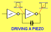
Driving a piezo from two Schmitt Inverters
Two gates are required and in the diagram each output is out-of-phase. This means one side of the piezo
is seeing a positive voltage while the other is at 0v. The outputs then change
state and the first side sees 0v and the second side sees a
positive voltage. This means the piezo see a voltage that is twice the supply
voltage and the output is slightly higher than if driven by a voltage equal to
the supply.
Understanding the concept of 2V (twice the supply voltage) across the piezo is
very important as this also applies to LCD screens in watches etc.
The closest analogy is this: Suppose you look at the top of a 10ft post. You
are then instantly transported to the top of the post and look at the ground.
The angle of your eyesight is firstly up, say at 45º then down at 45º. The
total travel of your eyes is 10ft plus 10ft = 20ft.
This is exactly what the piezo sees.
3.
Adding a choke across a piezo diaphragm produces an "OSCILLATORY
CIRCUIT." An Oscillatory circuit is very similar to a "RESONANT circuit" or
"TUNED circuit" however the output is not necessarily a peak value.
An oscillator circuit means that some of the effect of placing a coil and
capacitor in parallel, is achieved.
Again, to understand how this arrangement operates, we will have to go into
the theory of a parallel tuned circuit.
We have already mentioned that a piezo diaphragm is effectively a capacitor of
approx 22n. If we place a coil across this, we have a parallel tuned circuit.
The value of the coil is not important however 10mH produces very good results.
The way the coil and capacitor work is very complex. The exact operation is
not needed however an understanding of the operation will allow you to design
circuits with this arrangement.
When a pulse of energy is delivered to the combination, the coil forms a
blockage to the current while the capacitor is seen as a low resistance and
thus a small amount of energy is absorbed by the capacitor (the piezo
diaphragm).
When the supply is turned off, the energy from the capacitor is passed to the
coil (the choke) to produce magnetic flux. It keeps producing magnetic flux
until the energy from the capacitor has been fully delivered. At this point
the magnetic flux collapses and produces voltage in the turns of the coil that
is in the opposite direction to the previous voltage. This voltage can be considerably
higher than the initial voltage and is passed to the piezo. The piezo responds
to this high voltage by producing a higher output and when all the voltage
(energy) has been delivered, the voltage across the capacitor is passed back
to the coil (choke).
Energy will pass back and forth many times and each time the amplitude of the
signal will be lower.
However, the circuit turns on after the first or second oscillation, to
deliver another pulse of energy to the combination, with the result of a very
loud output.
If the circuit operates from a 12v supply, and is fed by a driver transistor,
the voltage across the arrangement will rise to 90v and even 120v as the
frequency is varied. At the point of resonance, the voltage is a maximum. If
this frequency happens to coincide with the natural resonant frequency of the
diaphragm, the output rises to 100dB and even 130dB.
This is the maximum level the ear can withstand and even at 3 - 4 metres, you
cannot hear anything in a room when this level of sound is being
emitted.
To produce the maximum output, the frequency delivered to the combination must
be the resonant frequency of the diaphragm and the choke must be wound to an
exact value. This is not always possible with standard components and
that's why piezo tweeters are available that produce up to 120-140dB
output.
One interesting point to note. The high voltage produced by the coil/capacitor
combination means the driver transistor must be able to withstand the voltage.
If the supply is 12v and a 50v transistor is used, it will zener at 50v and
prevent the piezo diaphragm receiving the full potential.
That's why a high voltage transistor must be used!
4.
From the discussion above, you can see the piezo diaphragm has a resonant
frequency and as the tone is raised and lowered, a peak in output is detected.
If the diaphragm is operated at this frequency, the output is a maximum.
Some manufacturers provide this frequency in the list of specifications.
PIEZO SPEAKERS
AND TWEETERS
The piezo diaphragm can be used as a speaker. Although its quality is not
equal to a "cone speaker," it can used to to accentuate
high-frequency signals in a passage of music. A piezo speaker consumes much less power than a
cone-speaker
and is able to produce sounds up to and beyond 135dB.
To produce voltages considerably higher than the supply we need an
inductor or a step-up transformer. When using an inductor, it is placed
across the piezo so that when current is passed through it and switched
off rapidly, the magnetic field in the inductor collapses and produces
a very high voltage. This can be as high as 50 - 80v for a voltage
as low as a few volts and these peaks are fed into the piezo to generate
a very loud sound.
The structure of the piezo is such that the brass diaphragm forms
one plate of a capacitor and the silvered surface forms the other.
The piezo material is a dielectric and produces a capacitor of approximately
3nF.
When an inductor is placed across a piezo, the two components form
a resonant circuit. We have already explained how a resonant circuit
works in other articles and basically the two pass energy back and
forth between them. The system is started by applying a voltage across
the two. The inductor creates a magnetic field and when the current
is turned off, the magnetic field collapses and produces a very high
voltage. This voltage appears across the piezo and a loud sound is
generated. The piezo does not use up all the energy and some of it
is fed back to the inductor to be converted to magnetic flux. This
is repeated back and forth between the two many times, each time
with a slightly reduced value and produces a ringing sound from the
piezo that gradually fades away.
Instead of the inductor, we can use a step-up transformer. This will
produce an AC voltage for the piezo and once again, the piezo will
produce a loud output.
The piezo diaphragm produces the highest output at a frequency called
the
PIC LAB-1 AND THE PIEZO
We have now covered the technical details of the piezo diaphragm and you will
have some idea of how it operates as an input and output device.
Connecting it to PIC LAB-1 is very simple and it's just a matter of
providing the correct interface and writing a program.
When connecting the piezo diaphragm as an input device, an amplifier is needed
to increase the amplitude to digital level. This will require two stages
of amplification to guarantee a rail-to-rail waveform.
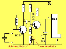
The diagram (a) below shows a two-stage amplifier. The output of the
piezo is amplified approx 100 times by the first stage and this signal is guaranteed
to turn on the second stage. The second stage is held in "cut-off"
by the 1M and 47k resistors. With a supply rail of 5v, the voltage on the
base is slightly less than 0.5v and this is below the voltage required to turn
the transistor ON.
A waveform less than 300mV from the first stage will raise the base voltage of
the second stage to a point where the transistor conducts and the collector
voltage changes from HIGH to LOW. This is detected by a program.
Diagram (b) shows the
circuit provided by PIC LAB-1. The supply resistor and electrolytic to
the input terminals are needed for the electret mic and are
not needed for the piezo. However they do not affect the operation of the circuit.
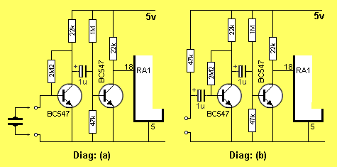
When connecting the piezo as an output device, a transistor having sufficient break-down voltage capability, must be used. This applies when a coil (choke) is added across the diaphragm.
WRITING AN
INPUT PROGRAM
The interface circuitry can be designed with a pulse extender to make sure the
signal is not missed. The electrolytic (1u to 10u) on the input line is discharged when the
transistor is activated and it takes time to charge. The "LOW time"
can then be detected by the micro.
To Top
The interface circuit between the piezo and microcontroller must produce a
digital waveform, (5v excursion) for the audio being detected. It is then a
simple matter to poll the input line on a regular basis to look for the
signal.
To detect the frequency of an unknown signal, a very clever program can
be produced to create a varying-width window. This will prevent the signal
synchronising with the window and not being detected.
Audio
Audio2
Audio3
Audio4
CLRF 13h
MOVLW 0A0h
MOVWF 1A
MOVF 1A,0
MOVWF 1B
DECFSZ 1B,1
GOTO Audio3
BTFSS 05,1
GOTO Audio4
INCFSZ 1A,1
GOTO Audio2
RETURN
INCF 13h
GOTO Audio2 ;File 13h counts
audio "lows"
;Create 50h loops! Yes 50h
;Copy 1A to W
;Copy W to 1B
;Look at audio input. Audio = LOW
;Increment file 1A to zero!
The program above will not be needed if a pulse-extender is added.
The circuit below shows a pulse extender:
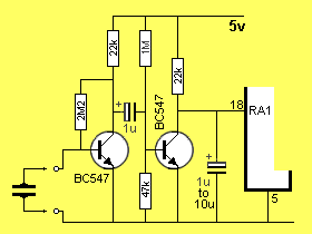
By adding the electrolytic, the circuitry can be made very insensitive so that only loud audio will be
detected. The diagram below
shows the addition of a 100k to reduce the voltage on the base of the second
stage. This pot also reduces the impedance on the base of the transistor and
this also reduces the sensitivity.
When the pot is turned to the HIGH Sensitivity end of its travel, the energy
in the 1u electrolytic will have to raise the base voltage from about 0.3v to about 0.6v to cause
the transistor to change state.
When the pot is turned to the LOW Sensitivity end, only about 22k is between
the base and 0v rail. The 1u will have to raise the voltage from about 50mV to
600mV. The low impedance of the base (the 22k between base and 0v) will
require more energy from the 1u and this will also have an effect on lowering
the sensitivity of the circuit.
![]()