|
Solar 5v Supply 1.
Solar Charger |
This projects uses two Solar Garden Lights.
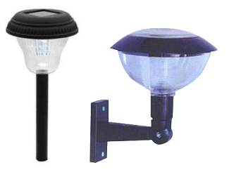
These lights cost less than $3.00
each and come with a 2.5v solar panel capable of charging at up to 35mA, a
rechargeable 1.2v NiCd cell and a circuit we will use to convert the 1.2v +
1.2v to a 5v output.
The two lights are dismantled and all the parts taken off one of the PC
boards.
We will be using both NiCd cells in series and the solar panels are placed
in series to charge the cells.
The circuits for these Solar Garden Lights are different, depending the
manufacturer, however they all do the same job.
The type we have used consists of an oscillator running at about 50kHz and
produces a square wave with a high of 60%.
The driver transistor receiving this waveform takes one end of a 100uH
inductor to the 0v rail. The other end is connected to the positive rail.
The resistance of the choke (inductor) is fairly important and the ones we
tested had a DC resistance from 1.7 ohms to 4.2 ohms and all produced the
same output. An inductor with a resistance of 13 ohms did not work.
When the transistor turns off, the spike produced by the inductor is passed
though a high speed diode to charge a 100u electrolytic. The voltage
produced by the inductor is actually about 12v - 18v but this spike is
absorbed by the electro and its voltage gradually rises.
When it rises above 5.5v, a voltage divider made up of a 1M and 150k,
creates a voltage of 650mV across the 150k and this turns on the PNP
transistor to shut off the oscillator.
Normally, the detection-line to the oscillator is used to detect when the
cells are producing a voltage and this shuts off the LED, as the Garden
Light determines it is daylight.
This sense-line detects less than a few millivolts to turn on the LED and
about 300mV it turns the LED off. This is a very wide gap and is designed to
prevent "Hunting."
If we connect directly to this sense-line we will get a 300mV pulsing
output. This is called Hysteresis - a condition where a circuit does not
change state until a higher voltage is reached and then does not change back
again until the lower voltage is reached.
To reduce this Hysteresis, we have added a PNP transistor. This reduces the
Hysteresis by a factor of about 100.
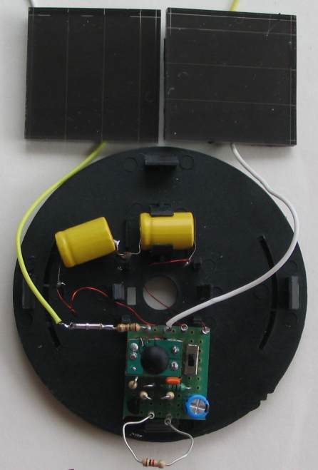
The two solar panels, 2 cells and matrix board
with a 1k load resistor. The 1R in series
with the solar cells detects charging current.
Use a multimeter set to mV. Each mV
represent 1mA charging current.
The circuit is designed around a "flyback Oscillator." This consists of an oscillator running at a high frequency.
The output drives a transistor that is connected to an inductor. An indicator is a coil of wire wound on a metal or ferrite material. It can also be wound with an air core but it will not have the same output in this circuit.
When an inductor is paced across a battery, it will not allow a high current to flow immediately. A small current flows and this produces magnetic flux and the flex cuts the other turns of the winding to produce a voltage in the opposite direction. This voltage opposes the incoming voltage and the result is only a very small voltage. This small voltage only allows a small current to flow.
The magnetic field is constantly increasing and this is called expanding flux and this expanding flux does not produce quite the same amount of reverse voltage in the winding due to the permeability of the magnetic material. So the effective incoming voltage becomes higher and this produces a higher current.
All this is happening in microseconds but eventually the current is a maximum and core is saturated with flux and it cannot produce a higher density of expanding flux. This is the point at which we need to turn off the transistor as the inductor is FULL of flux. Keeping the transistor turned on for a longer period of time will just waste current.
The transistor is now turned off and you can consider it is removed from the circuit.
The current ceases to flow and the magnetic flux collapses.
This collapsing magnetic flux produces a voltage in the winding that is opposite to the original voltage and because it collapses very quickly, the voltage is very high. It can be 5 times higher or 100 times higher or even 1,000 times higher.
It depends on the magnetic material of the core and a number of other factors. This is called the "Q" factor or Quality factor of the inductor and is one of the amazing things in electronics.
In our case the voltage is over 18v . But we do not want a voltage this high and you will see how we use this voltage in a moment.
We pass it though a diode to charge an electrolytic. The diode prevents the voltage on the electrolytic passing back into the transistor/inductor circuit and discharging.
The electrolytic gets charged with the energy of the spikes and will charge to almost 18v. To prevent this, we detect when the electro is 5v and turn off the oscillator via the "sense" line.
When the voltage drops below 5v, the oscillator is turned on again.
The circuit is called a "flyback" circuit because we use the high voltage developed during turn-off to deliver a voltage to the output.
It can also be called a "boost" circuit.
The other sections of the circuit have already been discussed.
CHARGING THE CELLS
The two solar panels are connected in series to charge the two 1/3 AA Ni-Cd cells.

1/3 AA Ni-Cd cell
The two 1.2v NiCad cells have a voltage across them of about 1.3v +1.3v
when charged and this rises to 2.7v when the panel starts to charge them.
This is called a "floating charge" and the voltage developed across a
cell when it begins to charge. This voltage has to be taken into
account when supplying a charging voltage. On top of this we have a diode to prevent the batteries
discharging into the solar panels (when no light is present) and this
makes the panels need to produce over 3.3v to start the charging
process.
With a high level of sunlight, the panels will deliver a charge-current
of about 35mA. Depending on the number of hours of sunlight compared
to the number of hours the project is required to deliver 5v, the
maximum amount of current you can draw is determined by the following:
The cells have a 130mAh capacity and if you charge them at 35mA, it will take 4 hours.
On most days the cells will be fully charged in this time and you can allow the
project to draw about 20mA during the charging process and still produce
fully-charged cells on a bright day.
This gives 8 hours of daytime use.
The night-time use must come from the cells.
If you draw 5mA from the 5v output, the current from the cells will be
13mA
to 18mA
and they will last a further 8 hours. This gives a total of 16 hours of
use per day @5mA.
This is only a very small current but the project is intended for
monitoring where it is turned on for a very short
period of time to collect data and store it or transmit it via an RF link.
You cannot expect too much from a $10.00 solar project with battery
back-up.
ASSEMBLY
The parts are placed on a small matrix board 8 holes x 10 holes. The PC
board from the Garden Light is cut so that only the chip and surrounding
lands are on the board.
This board is then connected to the matrix board via 4 short lengths of
tinned copper wire.
All the other components are fitted to the matrix board as shown in the
diagram. It is a simple matter to join each of the components
under the board with fine tinned copper wire (included in the kit).
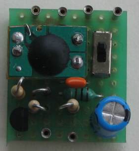
The top of the Matrix Board showing the
placement of the parts
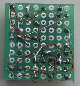
The underside of the board is very messy
and the parts need to be re-laidout so
that no wires cross over. It can then be made
into a PC board.
TESTING
When the power is applied, the output voltage will rise
to about 5v. The circuit needs a slight load to prevent hunting and a 1k
resistor will draw 5mA.
If the load is removed, the output will hunt and the current consumption
will drop to less than 1mA.
There are lots of different Garden Light circuits and you may need to
adjust the value of the voltage-divider to get the output voltage you
need for the circuit or the chip you are using.
You need to check the voltage on no load to make sure it does not rise
above 5.5v if you are using a microcontroller. If it rises above
5.5v and is not stable, you can add a white LED and red LED in series to
get a zener voltage of 5v1. Alternatively you can set the voltage to
below 5v and prevent over-voltage.
|
|
|
COMMENTS
Add your comment to the article by emailing
Colin Mitchell.