SPOT
Page 1
Page 2
Page 3
Page 4
Page 5
Page 6
Page 7
Page 8
Page 9
I can't work out what he is talking about, and I have studied the 555 for 25
years !!!
The "STOP" should be called "RESET."
THE MISTAKES!
Page 23
Page 10
Page 11
Page 12
Page 13
Page 14
Page 15
Page 16
Page 17
Page 18
Page 19
Page 20
Page 21
Page 22
Page 24
Page 25
Page 26
Page 27
![]() These pages are one of the most important features of our website.
These pages are one of the most important features of our website.
They show how easy it is to produce a mistake.
It's very easy to forget to include something, but it is unforgivable to state
something that you haven't researched or checked (by simply Googling the answer).
We
all thought Google was a made-up word until its meaning came through as the
"amount of money you need to retire on" -
$10100
A $1,000 life insurance policy in 1920 could buy a double-brick
house. In 2104 it does not pay for a coffin.
You need $1,000,000 to retire comfortably and this will just buy a rental
property to provide a good living.
What will be the statistics in 20 years?
That's why you need a plan to set-up a business that will see a good return so
you can
buy into the rental market.
Houses are the only reliable safe-guard. Everything else can rise and fall.
You need to think of a product you can market and promote for years to come.
And electronics can do this if you look into the fields of health, aids, and toys.
They are all areas where hundreds of thousands of units are sold and if you
simply look around and see something that YOU need, chances are OTHERS WILL NEED
THEM TOO.
![]()
My biggest regret with TE website is this: I didn't organise it as an
ENCYCLOPAEDIA.
There are so many facts and circuits on the site that it will fill a book.
Most of the information is NEW and not just a re-gurgitation of text-books from
the past.
Text books are wonderful. But they are frustrating. They explain a point in such
a way that the beginner doesn't understand what is being said.
Two facts come to mind:
No text book has explained how the protection diodes on the input of a CD4001 or CD4011 discharge
the capacitor in an oscillator.
Text books also say:
A collapsing coil produces a voltage IN THE OPPOSITE DIRECTION.
The word: "back EMF" does not have the same impact as saying: the voltage is
produced in the REVERSE DIRECTION.
Once you realise it is a REVERSE VOLTAGE, you can understand how a TUNED CIRCUIT WORKS.
However I made a huge change to the website when I introduced "frames" and added
the left index. This allowed easy access to all the folders.
But if I had added alphabeticalisation and links within each of the articles, the
reader would be able to refer to other articles in the website.
Fortunately we have an answer.
Simply use Google. Type: talkingelectronics.com tuned circuit
into the address bar and within 0.001 seconds you will have all the occasions
where I have used this term.
Every word in every sentence of Talking Electronics website has been indexed by
Google.
That's the power of the "robot."
![]()
Here's some more mistakes from Mike Tooley's text book:
There is No TR1, no IC1, what "buffer" ???
How do you expect a beginner to understand this gobbeldy gook !!!
You can buy a complete IR temperature "gun" for $25.00!!
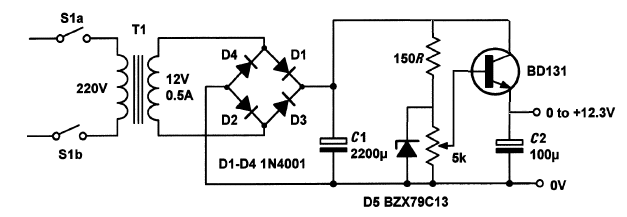
REGULATED
SUPPLY
These circuits produces a sinewave very nearly equal
to rail voltage.
Mike Tooley says: This is the book that I wish I had
when I first started exploring electronics nearly half a century ago.
Here is a paragraph from 2015 "Teach-In." The maximum total power dissipation is important in a number of applications,
particularly for devices where appreciable power is being delivered. In the case
of this family of devices, the total power dissipation (the sum of the power dissipated
in the two junctions) should be no more than 500mW. So, in an application where the
collector-emitter voltage is 15V and the collector current is 400mA the device will
be operating outside its maximum permissible ratings even though the collector-emitter
voltage and collector current do not individually exceed the manufacturer�s specification.
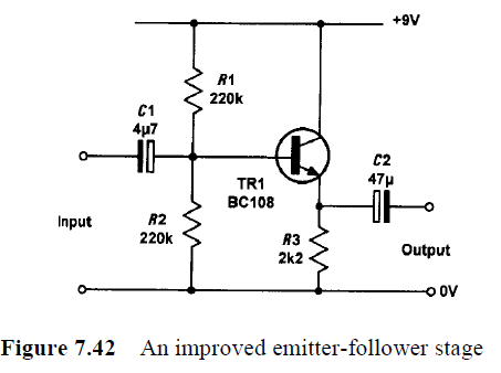
Here we have a pre-amp circuit for beginners.
Although the circuit may work, the 680R resistor between the base and 0v rail
will reduce the signal to less than 10% as the input impedance of the transistor
is about 5k.
This is NOT TRUE. The transistor may be able to "pull-up" and deliver a current
to the load via the electrolytic. But when the transistor turns OFF, the two
items that DISCHARGE the electrolytic are the 1k resistors. (2k total).
If you don't discharge the electrolytic, the transistor cannot charge it during
the next cycle.
Here is the "junk" PC board designed by Mike Tooley for the 2-transistor
amplifier circuit above. It has no overlay.
PC boards made by Chinese manufacturers cost LESS than doing it yourself.
It is a common base stage.
Mike Tooley says: "where direct voltage is amplified as well as AC."
I have NEVER heard of: "direct voltage."
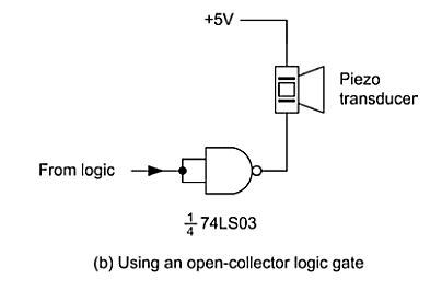
How does the circuit remove the charge on the capacitor (the piezo is a
capacitor) when the output of the chip is "OPEN COLLECTOR."
How is the circuit improved ???? Mike Tooley
does not say !!!!!
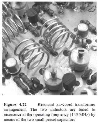
Mike Tooley claims these two coils make a transformer. They are so far
apart that the magnetic flux from one coil will have very little effect on the
other. The magazine subscription figures seem
very low and it would be almost not worth publishing. The projects they
offer are usually quite good in my inexperienced opinion but with the
variety offered and the fact that with electronics every reader's level of
experience is different it makes it hard to find the right balance between
simple to make and in some eyes a waste of time and money to being too
expensive or complicated for the average reader.
Here's more rubbish from Mike Tooley:
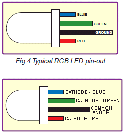
Mike Tooleys text book has 2 pages on the LED. He does not mention the fact
that the colour for each LED produces a different characteristic voltage drop
across the leads.
This is another bad example. It's a very bad policy to have a
transistor operating in any mode other than completely turned ON or completely
turned OFF.
Which transistor is TO-218 package ??? He explains NOTHING
!!!
All the writings in this books are simply a re-gurgitation of things you can
find in ANY text book. Nothing has been explained in a way that is NEW or
easy for a beginner to understand.
Take the Regulated Supply for example.
The output transistor is actually an EMITTER-FOLLOWER and when you draw the
circuit as shown in the second diagram, this is obvious.
The pot forms a voltage divider in which the slider (the wiper) is picking off a voltage
from 0v to 13v from the outer track of the pot.
This is passed to the transistor and it "rises and falls." The
emitter lead is the output and it is always 0.7v below the voltage on the base.
That is why it is called a "follower."
But the transistor provides an additional feature.
The emitter voltage is much smoother than the voltage on the collector. And this
is why:
As you increase the voltage (by turning the pot), the current required by the load will increase and
the voltage on the 2,200u can drop from say 15v to 14v. This is because the
electrolytic is like a miniature rechargeable battery and it charges-up when the
voltage is high and delivers its energy when the voltage is lower.
But when the current you are drawing for the circuit increases, the electrolytic
cannot deliver enough energy and the voltage "dips." There will be 100 "dips"
for a 50Hz input from the mains.
If you deliver this voltage directly to an amplifier you will hear a lot of
buzz and hum. But if you are able to use the voltage UP TO 14v, the result will be
perfect.
That's what the transistor does.
It just uses the voltage from 0v to about 13.9v so no hum is delivered to the
output.
So, what happens in reality is the output voltage can reach a maximum of 12.3v
and the 15v appears on the collector so the transistor "deals" with 15v - 12.3 =
2.7v across the collector-emitter terminals (collector-emitter junction).
The voltage can go as low as 14v - 12.3 = 1.7v across the junction.
The transistor can only perform this "magic" with currents up to 350mA because
the transformer can only deliver 500mA AC and when this is passed to the
transistor, the current must be de-rated.
WHY?
Because the wattage delivered by the transformer is an AC rating of 12v
and 0.5 amps = 6 watts. The 12v is an RMS value and when it is rectified, it emerges from
the bridge as a peak value. This value is 40% higher than 12v and becomes 17v. So, to keep the
wattage emerging from the rectifier 6 WATTS, we must DE-RATE
the current by 40%. In other words xxmA x 17 = 6
xx = 6/17 = 350mA
This explanation has been missed by Mike Tooley. He
said the circuit is capable of supplying up to 500mA. This is UNTRUE.
Instead of my simple explanation, he says the transistor is used to provide
current gain. How is a beginner supposed to know what that means????
He doesn't explain ANYTHING.
But what he is trying to say is this:
The zener is providing a stable voltage of 13v. If you use a high-wattage zener and a
high-wattage wire-wound pot, you could get 0v to 13v from the wiper (slider) and remove
the transistor.
But this would produce a lot of wasted heat and the circuit would be very
inefficient and completely "unregulated."
By using a transistor we can reduce the wattage of the zener to 1% and the
wattage of the pot to
1% and get REGULATION. This is because the transistor has a gain of 100. We are saying the
transistor has a gain of 100 to make our discussion easy to understand.
The transistor will amplify the current one-hundred-times. It will amplify the
current into the base one-hundred-times.
This is what he means by the transistor is used to provide current gain.
The current into the base will be multiplied 100 times
and this is the maximum current that can be delivered by the collector-emitter
leads.
But Mike Tooley does not realise the current into the base is very small. He has
not worked out the actual current that will be delivered as the pot is rotated.
This value MUST be worked-out if you want the circuit to work.
This is called the CURRENT-SIDE to designing the power supply.
The output current will be 350mA, so the base current will need to be 3.5mA.
This 3.5mA will be "robbed" from the zener.
In other words, the zener must pass more than 3.5mA because we will be taking
3.5mA from it.
The voltage on the 2,200u will be 12v x 1.4 - voltage drop across two diodes =
15.4v
The zener voltage is 13v so the current through the 150R will be 16mA.
The zener is passing 16mA and we want to rob 3.5mA. This part of the
circuit is correct.
BUT:
The current through the 5k pot will be as low as 2.6mA when it is turned towards
the 0v rail. So you can see the pot will not be
able to deliver the 3.5mA required by the transistor.
The pot should be 1k. But a 1k pot will allow 13mA to flow and this will make
the pot very HOT.
This is where the circuit "FALLS OVER." It has not been tested or
designed correctly.
The transistor actually has a maximum gain of 70 and is a very poor choice for
this circuit.
The end result is: THE CIRCUIT DOES NOT WORK.
SINEWAVE OSCILLATOR
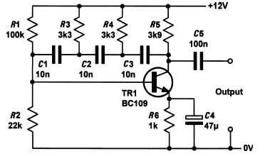
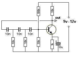
The important feature is the need for the emitter resistor and 10u / 47u bypass
electrolytic. It is a most-important feature of the circuit. It provides
reliable start-up and guaranteed operation. For 6v operation, the 100k is
reduced to 47k.
The three 10n capacitors and two 10k resistors (actually 3) determine the
frequency of operation (700Hz).
The 100k and 10k base-bias resistors can be replaced with 2M2 between base and
collector.
This type of circuit can be designed to operate from about 10Hz to about 200kHz.
Both these circuits are NOT VERY RELIABLE. They work with some transistors
better than others. They stop working when you touch some of the parts. The
frequency changes when you add a 100u across the power rails. They are too
fiddly to be recommended. Place a piezo diaphragm across the collector load and
experiment yourself. Try changing the 1k and try 6v to 12v to see what I mean.
Apart from the fact that many of the explanations are given in a complex way,
nowhere in his book does he mention the TUNED CIRCUIT. This is the most
important building block to be invented. It pioneered the ability to transmit a
signal over a long distance with very little power and obviously was the basis
to RADIO. Without radio we would not have TV, RADAR, internet and the most
important thing of all APPLICATIONS ON iPHONES.
He also mentions the inductor and the fact that the voltage produced by a
collapsing magnetic field produces "back e.m.f "
But that will go over the head of a beginner without saying this is the most
amazing thing of all. The voltage produced by an inductor (when it is turned
OFF) produces an OPPOSITE POLARITY VOLTAGE (to the supply voltage) - a voltage
IN THE OPPOSITE DIRECTION.
Once you know this, you can work out how a capacitor and coil in parallel
produce a natural sinewave without any other components. And the voltage they
produce can be TWICE the value of the supply !!!! It is called a TUNED
CIRCUIT or TANK CIRCUIT (when referring to radio circuits and
transmitters).
Mike Tooley has never learnt how to draw circuit diagram. That's because they
don't mean anything to him. He draws 555 blocks with pins "all over the
place" and connections to these pins all over the circuit.
In fact he has hardly covered the 555 at all. This is one of the most popular
chips and he has only shown a few circuits.
Also he has not even covered the most universal Schmitt Trigger IC - the 74c14.
This is a hex Schmitt Trigger with an enormous number of applications.
As I said, it is obvious he is not a "down-to-earth" design engineer and cannot
relate to the circuits because he has never even built any of them.
One FLIP-FLOP circuit does not make you a DESIGN ENGINEER.
His book is like giving you all the fancy LEGO BLOCKS without the 3 BASIC
BLOCKS. What can you build ??
No transistor circuits, no gate circuits, no microcontroller circuits - no
nothing.
What is he talking about ???
I don't know. How can a beginner understand this ???
You don't calculate 500mW by multiplying 15v by 400mA. 500mW is determined
by measuring the voltage across the collector-emitter terminals when 400mA is
flowing. The voltage might be 300mV to 800mV.
If the transistor is turned on FULLY, the collector-emitter voltage will be
about 300mV. If the current is 1,000mA, the dissipation will be 300mW. (1,000 x
0.3)
If the base current is not sufficient to FULLY turn the transistor ON, the
collector-emitter voltage will be higher than 300mV and can be say 800mV. In
this case the dissipation will be 1,000 x 800 = 1,000 x .8 = 800mW and the
transistor will overheat.
Here's more "technicalese" that needs simplification. Remember, he
is supposed to be talking to BEGINNERS:
The above may be correct but it is not easily understood.
Here is a simplification:
Amplifiers have four terminals (two for
the input and two for the output). The input is connected between the base of
a transistor and 0v rail. The output is connected between the collector and 0v
rail.
This way of connecting is referred to as COMMON or SIGNAL GROUND,
as the 0v rail is common to both the input and output.
What does this mean: "both
of the supply voltage connections to an
amplifier are common, at least as far as
the signal (AC) is concerned."
What he is trying to say is this:
All circuits have a "top" and "bottom" rail. These are called the SUPPLY. The
top rail is called the SUPPLY RAIL and may be 6v, 9v 12v or as high as 100v.
The bottom rail is called the 0v rail. If you are working on automotive
circuits, it can be called CHASSIS or "earth."
Don't ever talk about the supply as being a short-circuit.
But you can say the resistance between the positive and 0v rail is very very
small. Because this resistance consists of the effect of an electrolytic across
the supply rails and the internal resistance of the battery or power-supply
delivering the voltage and current to the project. We say the IMPEDANCE of the
supply rails is very small.
We only talk about resistance when we have a 1 ohm to 1M resistor in a circuit. If we have a
speaker, coil, transistor or capacitor in the circuit, the resistance we measure
with a multimeter will be different to the "resistance" seen by the circuit
WHEN IT IS WORKING and that's why we use the term IMPEDANCE.
The 4u7 will also reduce the signal a small amount.
But why teach beginners with a poorly designed circuit ????
I have never seen this type of circuit used to amplify a 600 ohm source.
Why reduce the signal to 10% then amplify it ????
The three resistance values are FAR TOO LOW for a small signal amplifier. They
should all be at least 10 times larger.
Mike Tooley has absolutely no idea what he is doing. If he doesn't know,
how do you expect a beginner to understand???
This type of circuit is actually divided into 3 different categories.
SMALL-SIGNAL AMPLIFIER, MEDIUM-SIGNAL AMPLIFIER and LARGE-SIGNAL AMPLIFIER.
(SMALL-SIGNAL STAGE, MEDIUM-SIGNAL STAGE and LARGE-SIGNAL STAGE.)
What we are really saying is "small-current" "medium current" and "large
current." The current in a "large current stage" is MUCH LESS than a
POWER STAGE.
The circuit above is called a "medium signal stage" and is NOT interfaced to a
600 ohm signal. A 600 ohm signal is classified as a medium-impedance signal and
must be interfaced to a medium-impedance stage to get good matching and allow
most of the signal to be signal to be accepted. There are always losses when
matching a signal to a stage when a capacitor is present on the input but adding
the 680R is totally unacceptable as less than 10% of the signal is passed to the
base.
2-TRANSISTOR AMPLIFIER
Mike Tooley claims the
output impedance of this amplifier is 30 ohms.
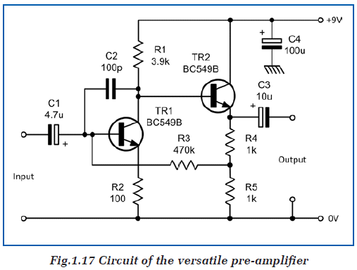
This fact has been completely forgotten by Mike Tooley.
He states the input impedance is 20k and output is 30R. And yet he uses 4u7 on
the input and just 10u on the output. This shows a complete lack of
understand of impedance-values.
I was the first person in the world to provide FREE PC boards with a magazine,
over 30 years ago, and they all had an overlay (called a LEGEND).
In addition, the name of the project was printed on the board. How you can
produce JUNK like this is beyond me. He obviously has no respect for
electronics.
In addition, putting R1, R2 etc on a board is pointless. All my boards can be
assembled without any further instructions as the component values are on the
overlay.
You can instantly identify a capable electronics engineer by
his work. This is sheer JUNK. The PC board costs $15.00 from Everyday
Practical Electronics. Who is going to pay $15.00 for a piece of junk like this: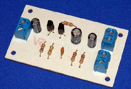
The board above is a double-sided, plate-through-hole with tinned solder-lands
and a legend on both the top and bottom.
It is made by Nicholas McClanahan, a hobbyist who takes pride in his work and
produces BEAUTIFUL boards.
This is the sort of quality that should be presented in Mike Tooley's text book,
to show the reader HOW things should be done.
Here's a piece of re-gurgitation I spoke about above: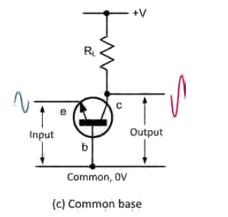
Although the arrangement is correct, a practical arrangement is different. More
biasing components are needed. The
operation of the stage is not covered in the text. Why include an impractical
layout for a beginner and fail to describe it. ????
The common base stage will interface (connect) a very low impedance transducer
(such as a speaker or coil) and amplify the signal 100 to 200 times with minimal
distortion because of the direct coupling. One or two practical circuits are
needed to show the value of the surrounding components.
The author is treating the readers as IDIOTS. He is asking them to buy a
magazine and then producing HOT AIR. You can get better information on the web
FOR FREE.
The Phase Shift for a common base stage is 0�. In other words, the
input and output are IN PHASE. The waveforms on the diagram above are NOT CORRECT.
The red output wave should be drawn "up-side-down."
Mike Tooley claims the voltage gain of common-emitter stage is Medium/High (40).
However the gain depends on how the stage is biased. Self-bias gives a gain of
about 70 but other biasing arrangements can produce 100 to 250 or more. Power
stages can be as low as 10 to 25.
Mike Tooley also talks about transistors with a gain of 100, 220 and 450. What
he fails to mention is this:
When a transistor is placed in some circuits, the resulting gain of the stage is
almost the same for any of the transistors.
It all depends on the way the circuit is biased. After all,
biasing is designed to maintain the same gain, irrespective of the temperature
of the transistor and also produce nearly the same stage-gain for a wide variety
of transistors.
It is only under very special circumstances that the full gain of the transistor
can be obtained. In fact it is so hard to determine the gain of a stage
before-hand, that you need
to build the stage and try different transistors to see if any variation is
produced.
The worst common-emitter stage has the base resistor connected to the positive
rail and the resistance of the collector load is adjusted to produce about
half-rail voltage on the collector. If the transistor is replaced or heated, the
collector voltage will rise or fall considerably.
The next worst common-emitter stage has the base resistor connected to the
collector. This is called SELF BIASING and the collector voltage will change
slightly if the transistor is heated or replaced. It is much better than the
worst stage but transistors with a gain of 100 will produce a high voltage on
the collector and a transistor with a gain of 450 will produce a low voltage on
the collector.
The next type of common-emitter stage has an additional resistor between the
base and 0v rail.
The produces a lot more stability but it decreases the gain of the stage
considerably.
Finally, biasing via 4 resistors in a "bridge" arrangement provides a high
degree of stability but the gain of the stage is reduced.
He also throws in things like this: Notice that there is a fair amount of
variation across the three gain groups. For example, the data shows that the
input resistance (hie) for a device in Group C could easily be more than four
times greater than that of a device taken from Group A.
He offers NO EXPLANATION - so why bring it up??????? He does not know the answer !!!
The reason is this: all the transistors are tested with a collector current of
2mA. To produce a collector current of 2mA with a transistor having a gain of
100, requires .02mA (20uA). To produce a collector current of 2mA with a
transistor having a gain of 400, requires 5uA and the base-emitter junction will
not be turned ON as much and it will "appear" to have a higher impedance.
His coverage of 5 band resistors is very poor. It is NON-EXISTENT.
5-band resistors are easy to read if you remember two simple points. The first
three bands provide the digits in the answer and the 4th band supplies the
number of zero's.
Reading "STANDARD VALUES" (on
5-band resistors)
5-band resistors are also made in "Standard Values" but
will have different colours - and will be confusing if you are just starting
out. For instance, a 47k 5% resistor with 4-bands will be:
yellow-purple-orange-gold. For a 47k 1% resistor the colours will be
yellow-purple-black-red-brown. The brown colour-band represents 1%.
He has 3 pages on soldering and NOT ONCE does he talk about the diameter of the
solder.
He has NEVER SOLDERED IN HIS LIFE.
You must use solder with a diameter LESS THAN 1mm.
0.8mm solder makes a much better connection than 1mm and 0.6mm makes a PERFECT
connection.
I have never seen this mentioned in any soldering articles.
Another wasted chapter is on MICRO's. He discusses the Z-80 and PIC micro in
general terms but does not offer any first-hand commentary.
the Z-80 was one of the first 8-bit microprocessors but needed an external
clock, RAM, ROM and decoders as well as latches to get anything up-and-running.
It had about 700 instructions but you very quickly ran out of registers to store
information.
Almost all the capability of a Z-80 can be handled with a PIC16F628 at $1.50 and
the PIC chip has only 35 instructions to remember. Out of these, you only use
about 10 on a constant basis.
He covers the 35 instructions (called mnemonics) because each letter of the
instruction represent a word in it capability. But he then presents a program in
"C" and never covers a program in ASSEMBLY (a program using the 35
instructions).
It's only someone like me, who has worked with both micros, that can review the
chapters and see how badly they have been presented.
A newcomer simply says: "microcontroller programming is NOT for me."
His text book has not give me any incentive to study electronics and you can
find more-exciting discussions on
Instructables or Make.
I also have a point-of-difference with the way he has described the operation of
a simple common-emitter stage.
The stage is biased with a base-resistor to the positive rail and although he
has described its operation correctly, this type of biasing is never seen in
reality as it depends HEAVILY on the gain of the transistor to maintain
half-rail voltage on the collector.
He covers the base current required to obtain mid-rail voltage and then talks
about a 15uA input signal to produce a 3v signal on the collector. This is all
correct, but in reality, how are you going to find, detect and view a 15uA
signal. You may be able to view all this on a simulation package, but in reality
a Cathode Ray Oscilloscope only displays signals with AMPLITUDE.
That's why you have to decide if you want to build "pretend" circuits or learn
how to diagnose actual circuits.
He should have made this clear to the beginner and gone on to describe a
self-biased stage.
What he has described is quite NON-FUNCTIONAL and useless.
Simply looking at the comments and mistakes above, it is clear Mike Tooley does
not have a firm understanding of the basics of electronics.
An email from
Mike Tooley confirmed my thinking. He has no idea how the Regulated Supply
(circuit above) works and how to comment about the mistakes.
We will see what mistakes appear in the second installment of Teach-In 2015.
I received this email today and I am going to respond to it because it brings up
two points from the current item.
If anyone sends and email with any derogatory comments I will also present them
too, because I intend to cover everything and not filter anything out.
This email comes from Dave Thompson NZ
Essentially the same four or five guys design projects for Silicon Chip
and while I used to subscribe to EPE I flagged it in the end because the
projects they were publishing were re-hashed Silicon Chip articles that
I'd already paid one subscription fee for.
I sent a letter to the editor
of EPE stating exactly that and they didn't deem it fit to print.
Still,
the quality of those projects is better than EFY, which I also subscribe
to, and which you show up a lot in your 'Spot the Mistake' pages.
I'm not
experienced enough to find mistakes as I'm nowhere near the level of
'seeing' circuits in action just by reading the schematic - part of me
going to TE is to try and up-skill so that I can get to that level but I think
it is something you either have or haven't - and I haven't.
Sadly in Oz and
NZ if you stick your head above the parapet you can guarantee someone with no skills and no hope at all will try to shoot you down and
that is a culture I cannot abide by - it keeps society in the dark ages
and squashes motivation.
If you want to
use anything I say as a testimonial on your site you
are welcome to do so.
Kind regards
--
Dave Thompson
dave@pcanytime.co.nz
Christchurch NZ
Thanks Dave,
I have had many comments from readers who have written to EPE and not received a
reply.
Many readers and advertisers have commented about the re-hashed articles from
Silicon Chip.
This whole interaction with EPE started when I offered 30 new projects and they were
FLATLY turned down.
On further investigation I learned from an advertiser that Matt Pulzer (the
editor of EPE) said he
could not accept projects because "they couldn�t accept
them because they had no way of checking them for accuracy."
Then I find Matt Pulzer saying he will learn a lot from the basic
"Teach-In" series.
The advertiser went on to say: "I don�t understand why people buy the magazine
when they could get the projects from Silicon Chip magazine by subscribing
to that magazine instead of waiting a couple of years to see them repeated in EPE."
The second thing I want to comment on is "SEEING A PROJECT WORKING."
I have been criticized by two electronics "PROFESSORS" for making such a STUPID
comment. How can a person SEE a circuit working ????
How do you think Whitworth SAW the wear on the teeth of his reduction-gear and
work out how to reduce the wear ????
He saw the problem in his "MINDS-EYE."
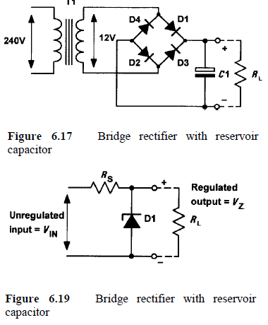
To see what I mean by "seeing a project working" we just have to take the Regulated Power Supply circuit above.
This is reproduced from the 3rd edition of a text book that would have seen by
10,000 readers, including lecturers, teachers and students.
NOT one person could see the fault in the circuit.
When I emailed Mike Tooley, he made a vague comment about the 12v AC
should be increased to 15v AC "to give the regulator headroom."
From this comment it was obvious he did not understand how the circuit worked.
That's why he did not explain it in his text book and that's why none of the
readers were any the wiser. The whole discussion was a WASTE OF TIME.
Don't you think I can detect the competence of a person after teaching for
over 30 years ?????
Just like I can recognise a politician after listening to 2 words, I can see if
a person understands what he is talking about after a few comments.
I can see Mike Tooley has never done any soldering, never made a PC board, never made a
project and never done any fault finding. He has never even looked at a 1%
resistor.
If he had done any of these things he would have mentioned the tricks and
traps to avoid.
He doesn't mention to use THIN solder, he doesn't mention that a 555 takes 10mA
when sitting around. He doesn't mention a 555 is not an ENGINEERS chip - it is
only suitable for automotive projects as it CROWBARS the power rails. His PC
boards are absolutely atrocious and if any staff member made a SHIT board like
his, he would be fired immediately. Even my first-year apprentice made boards I
was PROUD OF.
Mike Tooley has a cheek to put himself up as an instructor. Not once does he say
how the energy from a transistor stage is passed to the next stage. And he makes
stupid comments about the output of a stage is 30R when the pull-down resistor
is 2k. He does this because he cannot SEE a circuit working and that immediately
put him in a position of not being able to teach. Or more-accurately not
being ALLOWED TO TEACH.
It's no wonder Everyday Practical Electronics is going down the gurgler; like
the Titanic, it is just a matter of time.
The readership has plummeted in the past few years. Readers are seeing there is
nothing in each issue of the magazine.
The projects are "boring" and no-one is offering kits. None of the projects are
simple - for a beginner and the Forum is monitored - with negative
comments removed.
Teach-In posts on the EPE Forum, have dropped from 15,000 in 2010 to 75 posts in 2011.
And yet Matt Pulzer says Teach-In is one of the most popular articles in the
magazine.
The global acceptance of any website is indicated by Alexia and Talking
Electronics has a rating of
179,864 to represents 6,000 visitors each day.
EPE has a rating of 3,044,165 and Silicon Chip is 621,393
There is no direct relationship, however the equation can be 3,000 visitors a
day for Silicon Chip and 300 to 600 a day for EPE.
EPE offers nothing on their website except a JUNK soldering guide for $10.00
WHICH HAS NOW BEEN REMOVED !!!
If anyone has the slightest feeling that I have made an incorrect comment,
please email me.
These comments are only a FRACTION of what I am REALLY feeling.
The way people have been treated by Silicon Chip and Everyday Practical Electronics
is ABSOLUTELY ATROCIOUS and I can extend this to many of the text books I have
downloaded.
To charge $30.00 for a text-book filled with re-hashed re-gurgitated verbiage is
absolute dishonesty.
It is no wonder hundreds of visitors have said they have learnt more from my
website than all the University courses they have undertaken.
The only problem is this: I have only covered the very basics of electronics.
Once you get to higher levels, mathematics takes over and faulty thinking is less
evident.
No-one has covered the transistor amplifier in more details than me and after
300 circuits, I have only covered some of the circuits.
To put ONE circuit in a text book and call it COVERAGE, is beyond me. What does
Mike Tooley think he is doing?????
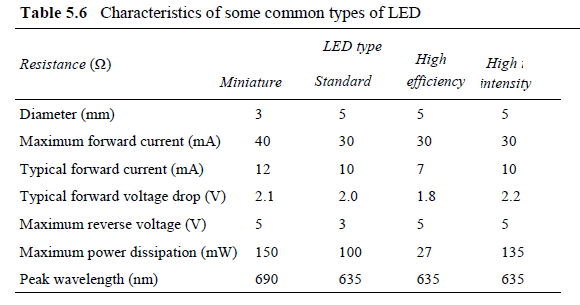
He does not mention the cathode lead is the lead which we look for when
identifying the leads and this is the shorter of the two leads and sometimes has
a flat spot on the side of the LED.
In the table above what does Resistance in
W mean?
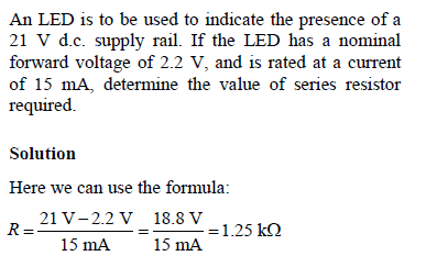
How is a beginner to know the colour of a LED that produces a wavelength of
690nm ??
I have NEVER connected a LED to 21v. What a STUPID exercise.
How can the same colour LED produce different characteristic voltages of 1.8v,
2.0v and 2.2v ???
This is just JUNK information.
I have produced 20
pages on the LED and he doesn't even show a photo of a LED !!!! 
During both of these conditions, the transistor is dissipating the least power.
In 50 years of electronics, I have NEVER had a circuit where a transistor has 6v
across the collector-emitter terminals and if you want to drop 6v @1.5amp, you
use a resistor.
In a regulator circuit you NEVER use the biasing to create the output voltage.
In other words, you NEVER partially turn ON a transistor to create the output
voltage.
The mere fact that you are creating a regulator circuit means the output voltage
is required to be stable and fixed.
This is the WORST test-question I have seen in my life. 
The wrong caption has not been picked up on the 3rd edition of the text book. I wonder who reads the book ???
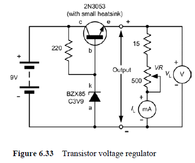
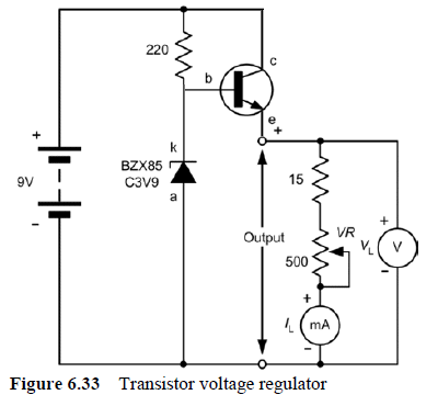
The diagram shows a transistor regulator. It's no wonder the student can't
learn anything from the text book. I don't know how the circuit works until I
change it to show the transistor operating as an EMITTER-FOLLOWER.
Now I can see the emitter will be 0.7v less than the base.
The gain of the transistor can vary from 25 to 250, depending on the collector
current.
The data sheet is vague and lacking any graphs to help with determining its
suitability for this circuit.
However the transistor is effectively reducing the 220R resistor by 220 (the
gain of the transistor) and thus the transistor becomes equal to a 1 ohm
resistor for the highest gain and equal to 9 ohm for the lowest gain.
This is just a quick, mental, way of assessing how the circuit will behave with
a 15R load and how you can see the circuit as a VOLTAGE DIVIDER.
These are the personal points Mike Tooley should be including in the text.
If you connect 9R and 15R in series, you will get more than 6v at the join and
thus the circuit will work as required.
This type of class-A amplifier is unsuitable or audio because it is very
difficult to get the collector voltage to sit at half-rail.
The gain of the transistor, the temperature of the day and the rail voltage will
alter the operating point and make the amplifier unreliable.
It's pointless covering this circuit however the explanation in the text is very
poor.
The operating point can be obtained by selection high values of resistance for
the base and load. This is called light biasing the transistor.
The values can be lowered and this is called medium biasing the transistor.
The values can be smaller and this is called heavily biasing the transistor.
The values must be chosen so the current entering the base via the capacitor
will no cause the voltage on the collector to rise to rail voltage or drop to
nearly 0v.
Look at this RUBBISH: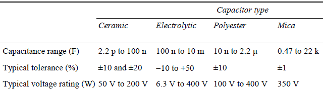
What does this mean: 100 n to 10m should be: 100 n
to 10u
What does this mean: 0.47 to 22k
should be: 0.47u to 22n
What does this mean: Typical voltage rating (W) should be
Typical voltage rating (V)
More RUBBISH:
All values MUST show the full nH, R or MHz
The first mistake is stating a voltage to two decimal places when the
resistors are either 5% or 10%.
A 10% resistor can be 10% higher or lower than the stated value and this is a
gap of 20%. When you get two or more resistors, the deviation increases 2, 3 or 4
fold.
No collector voltage will remain steady to a factor of 1/100th of one percent.
All data should be referenced to the component(s) having the worst tolerance.
The collector current is 3.2mA and the emitter current will be about the same.
This is not a high current and we can assume the transistor has a gain of 100 or
more. This means the base-emitter voltage will be about 0.7v and the emitter
voltage will be 1.3v.
![]()
This is just RUBBISH. It sounds like there is a whole range of transistors
designed for operation below 100kHz.
All transistors will operate at a low frequency. This is just a STUPID thing to
say.
Components should be drawn in the same position they will be placed in a
circuit, with an imaginary positive rail at the top. This is just another
INTELLIGENT thing to do to help the beginner. And they should be labelled.
they would appear in a circuit
![]()
![]()
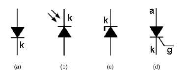
The transistor has been flipped over
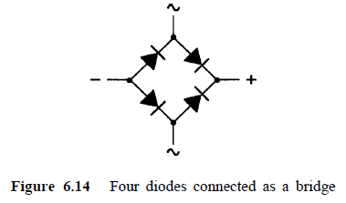
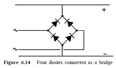
This diagram shows the input and output of the bridge
I like this layout because you can see the diodes all face one direction
The bridge can be replaced with a box and a single
diode showing the direction.
The box can be a diamond
All these transistors are very cheap on
eBay (25% of normal price) with free postage.
TIP31 has been added for TIP31/32 push-pull output.
(5 x TIP31/32 pairs for $3.00 posted)
Look at this stupid diagram:
It is a TOP VIEW !!!!
That's why I provide a full 3D sketch of the device, so you don't have to try and work out how it is connected.
Here is another poor diagram and the improved labeling shown in the second diagram:
Here is a "professional" solution to fixing a problem:
Look at the soldering and the parts-placement. This is NOT the sort of picture to print in an electronics magazine. What an embarrassment.
![]()
Here is a Flashing Christmas Tree circuit from Tandy:
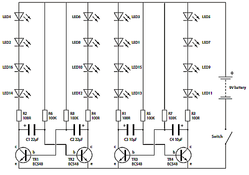
It has one major FAULT. The 4 LEDs in series will produce a characteristic
voltage drop of 1.7v x 4 = 6.8v and the voltage drop across the
collector-emitter of the driver transistor is 200mV. This means the minimum
supply MUST BE 7v. There will be a small voltage drop across the 100R resistors
(between 2v and less than 100mV).
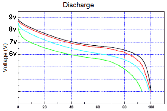
The voltage of a 9v battery drops very quickly when with a current of 10mA and
the circuit will stop working when the voltage reaches 7v. This represents only
about 40% of the life of the battery.
This is something to remember when designing a circuit.
Here's some junk audio amplifiers from:
Paradigm Technologies has over 35 years of experience in the electronic industry
with an extensive portfolio including test development, embedded system design
and digital signal processing. They have created many successful products during
this time.
Their range of amplifiers include LM380 and LM384.
The range of LMxxx amplifier chips absorb about 2 to 5 watts and MORE from the
supply and deliver some of this power to the speaker. However, some of the
wattage is produced by the components in the chip and this increases the
temperature of the IC.
Here is another STUPID circuit from Professor
D.Mohankumar.
What is the purpose of the 10u electrolytic when the input capacitor is 100n ??
Just another stupid circuit from the Professor who does not check or test
ANYTHING.
![]()
PARADIGM Technologies (UK) LT
Registered office address:
64 Blacksmith Close, Oakdale, Blackwood, Gwent, Wales, NP12 0BG
Company status: Dissolved on 29 December 2015
Fortunately this company has GONE!!!!
Paradigm Technologies range of kits will use the latest technologies from areas
such as audio,
solar, computing, displays, energy harvesting, battery/storage devices and
wireless
communication.
Paradigm Technologies have launched their initial range of electronic kits, with
many further kit and module releases planned for 2014.
Here are some of the PC boards: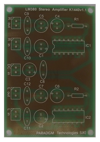
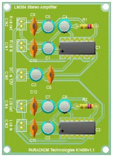
The 3 middle pins on each side of the LM380 and all the pins down one side of
the LM384 are connected to the output transistors inside the chip in the form of
a HEATSINK and although they are not electrically connected, they take away the
heat generated by the devices.
BUT the pins MUST be soldered to the copper laminate of the PC board so the heat
will be transferred to the board and passed to the surroundings.
The heat generated by the IC can be 2 watts or more and this requires at least
30 square cm of copper to prevent the IC overheating.
Ideally, the copper needs to be thicker than the normal copper laminate but this
can be done by tinning the board.
If you look at the boards designed by "Paradigm" you will see NO
heatsink provided by the board.
Paradigm Technologies has over 35 years of experience in the electronic industry
-
what have they been doing????
They have absolutely NO IDEA how to design an amplifier.
Simply connect the amplifier to an oscillator and listen to the response from a speaker. Put your finger on the chip and see how hot is gets.
The LM380 is a 2.5 watt chip and they say it is 4.1 watts!!
Paradigm was emailed with this information and they have NOT REPLIED !!!
They are trying to sell their faulty LM380 stereo amplifier kit for $30.00
You can by 3watt+ 3watt on eBay for $1.00 posted !!!
PAM8403 Audio Stereo Amplifier Board Class D Kit Module 2*3W USB Power
All kits are available from our official UK Distributor:
ESR
Electronic Components Ltd. www.esr.co.uk
The distributor was also notified and did not reply. Obviously he did not understand the concept of heatsinking an audio amplifier and he
will become "unglued" when a customer asks for a refund on a faulty design.
I am not "stirring the pot." The kits are absolute RUBBISH and
provide NO HEATSINKING. They simply will not work.
I don't mind losing $1.00 on a Chinese kit but $30.00 plus TAX and delivery on
a faulty project is annoying.
I checked the web for Paradigm Technologies (UK) Ltd on 1st July 2016.
They have "GONE."
![]() Water Heater Alarm
Water Heater Alarm
Here is an unusual circuit using a
capacitor-fed power supply. The circuit is badly designed and comes from a long
list of poorly designed circuits by Professor
D.Mohankumar.
He does not understand the concept of how a transformerless power supply works
because it is very complex.
Here's the circuit: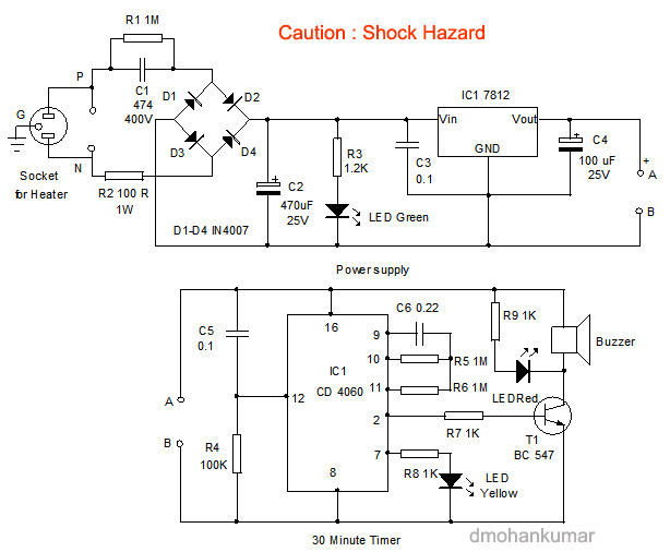
A transformerless power supply delivers 7mA for each 100n of capacitor C1. Thus 474 delivers
33mA.
This current NEVER changes and the output voltage of the supply depends on the
resistance of the load.
In other words, the output voltage will rise until the current through the load
is 33mA.
This concept is entirely different to any other power supply and that's why you
have to understand it.
The LM 7812 regulator takes between 5mA and 8mA and although this is not
important in a normal power supply, it makes a big difference in our circuit.
Suppose it takes 8mA. This leaves 25mA. Suppose the timing circuit takes 1mA,
this leaves 24mA.
This means the voltage on the regulator will rise to 30v and the 1k2 resistor
will take 24mA. This means 24mA will flow through the LED.
This voltage is more than the 25v allowable for the 470u electrolytic.
If the regulator takes 5mA, the situation is worse. 28mA will be available
for the 1k2 and the voltage across this resistor will be 35v.
When the timing circuit turns ON, the current through the 1k base resistor will
be 12mA. The transistor does not need this high current, however the
current is "robbed" from the LED and the 12mA flows through the regulator
to the chip and out the 1k resistor. The
input voltage on the regulator drops from 30v to 18v. Or 35v to 21v if the
regulator takes 5mA.
When the transistor turns ON, the LED on the collector turns ON and another 12mA flows
through the LED. This drops the input voltage to the regulator by 12v as it is
robbing the current from the 1k2 resistor. Suddenly we don't have 12v available
from the power supply because the input voltage to the regulator would drop to
6v or 9v.
We now have an unknown set of conditions where ALL the available current has
been taken by components and NOTHING is available for the Buzzer. All the
voltages will drop and some current will be available for the buzzer but it will
only be a few mA.
This is just another MESSY design by the Professor who does not check or test
ANYTHING.
![]()
What is the purpose of the 10k on the input when 100k is in series ???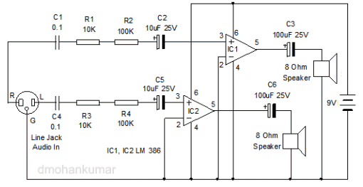
And he says I cannot "see" a circuit working. I can "see" these 4
components are NOT NEEDED.
![]()
Here is another STUPID circuit from Professor
D.Mohankumar.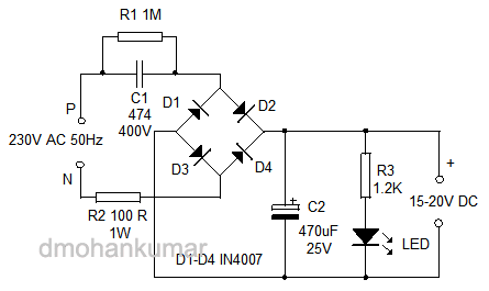
Here's why:
The 474 capacitor will deliver 7mA for each 100n = 33mA. The voltage across the 1k2 resistor will be:
V = I x R = 0.033 x 1,200 = 39 volts. The 25v electrolytic will BLOW UP.
The wattage of the 100R resistor needs to be I2 x R = 0.033 x 0.033 x100 = 0.1 watt NOT 1 WATT !!!
![]()
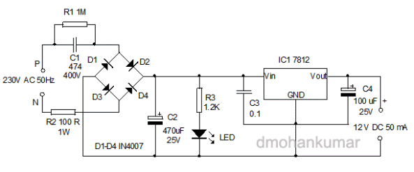
The 474 capacitor will deliver 33mA.
The 7812 regulator requires 8mA. This leaves 25mA.
The voltage on the output of the bridge will rise to 30v until 25mA is taken by
the 1k2 resistor.
This will leave NOTHING for the output of the circuit.
If you draw 13mA, the voltage on the input of the regulator will drop to 14v
and the regulator will start to drop out of regulation.
This circuit has obviously NEVER been tested. It can NEVER deliver 50mA.
It is just another JUNK circuit from
Professor
D.Mohankumar.
![]()
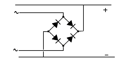
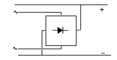
Look at this mistake in PRACTICAL ELECTRONICS HANDBOOK
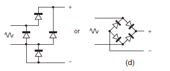
The input wires do not connect to the diode
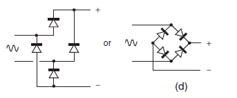
The corrected bridge circuit
Here's some DRIVEL about the circuit above: The author says: using a
complementary emitter-follower output circuit with no load resistor.
What does that mean ???
He then says: a complementary double-emitter-follower circuit which uses
transistors both to charge and to discharge stray capacitances.
What RUBBISH !!! How is a beginner going to learn anything about
electronics when this sort of rubbish is presented in text books.
This drivel comes from Ian Sinclair and John Dunton.
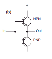
The circuit is a COMPLEMENTARY-SYMMETRY PUSH-PULL OUTPUT. It is effectively an
emitter-follower in BOTH DIRECTIONS and has a very low output impedance.
The circuit will drive an 8R speaker directly or via a 100u electrolytic. If the
gain of the transistor is 100,this will make the input impedance about 1k.
Go to The
Transistor Amplifier to learn more about this circuit.
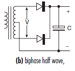
This is NOT a half-wave supply. It is a BI-PHASE FULL-WAVE POWER SUPPLY.
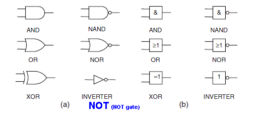
Neither Ian Sinclair or John Dunton have never done any Logic Designs.
They have forgotten to say the Inverter is a NOT gate !!!
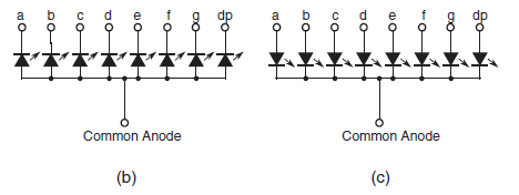
They both cannot be common anode:
The whole text book is just a jumble of topics where nothing is really covered
fully and not a single item is covered in enough detail for the student to say
he has learnt anything.
Everything in the text book is freely available on the web in MORE detail and I
wouldn't waste any more time looking though the book after downloading it from
the link above. It doesn't even rate a score of 1 out of 5.
It's absolutely pointless being
Trying to cover so many topics with such little information is a COMPLETE WASTE OF TIME.
I couldn't find many mistakes in the book because there was little factual material. Everything had been lifted from other text books or lists of pointless information - to fill the pages. The photos were all taken from the web and were the poorest quality possible. All the diagrams came from different sources and used different symbols.
It's really just a JUNK text book. Just add the .pdf to your computer, look through it, and don't waste any more time. For these simple mistakes to be present in the 6th edition, indicates its value as a text book.
Here's more RUBBISH from Professor D.Mohankumar.
Wattage is the capacity of the resistor to handle maximum current. Usually, � watt resistor is used if the current in the circuit is less than 50 milliamps.
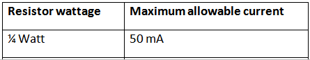
Wattage is the capacity of the resistor to handle maximum current.
This is NOT TRUEWattage is the voltage across a resistor MULTIPLIED by the current flowing through the resistor.
When the resistance is SMALL, the current can be HIGH.
Take the following examples:
For a 1R resistor, the current can be 250mA - the resistor can act like a fuse It will burn out when excess
For a 5R resistor, the current can be 225mA - the resistor can act like a fuse current flows
For a 10R resistor, the current can be 160mA - the resistor can act like a fuse
For a 22R resistor, the current can be 100mA - the resistor can act like a fuse
For a 100R resistor, the current can be 50mA
Here's a circuit from a reader who wanted me to help him create a PCB:
Before you create a PC board for a circuit, make sure the project WORKS !!
The circuit does NOT work. When one transistor is turned ON, the collector
voltage is almost zero and the resistor and electrolytic are connected to 0v.
There is no resistor connected to a voltage that will start to charge the
electrolytic and continue the cycle.
The two black resistors need to be removed and replaced with the two red
resistors.
The circuit will now FLIP FLOP !!!!
![]()
MELODY CIRCUIT
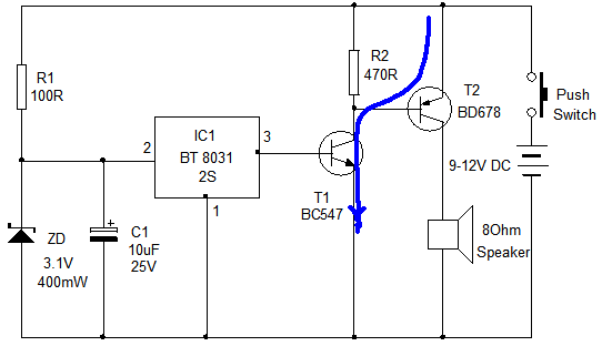
When the switch is pressed, the BC547 transistor will get turned ON and a high
current will flow in the collector-emitter junction. This current will not be
limited by the 470R resistor because the BD 678 transistor is directly connected
between the collector and positive rail.
BATTERY MONITOR
This transistor only produces a 0.7v drop across the emitter-base junction and a
very large current will flow though this junction.
Either or both transistor can be destroyed if a current-limiting resistor is not
fitted.
![]()
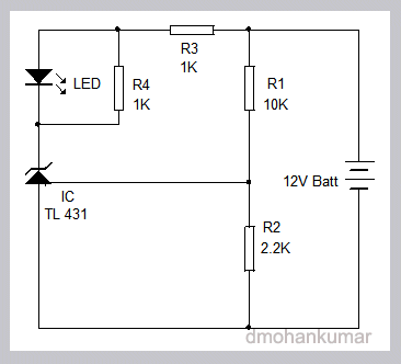
The circuit shows a 12 volt battery monitor circuit using TL431 Shunt regulator. It lights a Green LED when the voltage of the battery rises above 12 volts. Let us select the High limit as 13.8 volts which the voltage of a 12 volt Lead Acid battery after fully charged.
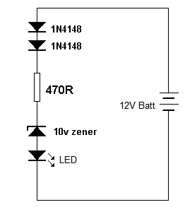
The circuit can be simplified to a 10v zener and dropper resistor. The 1N4148
diodes increase the detection-point by 0.7v for each diode. You don't have to
use an expensive, hard-to-get, TL431 device.
![]()
Here is a good example of how to analyse a circuit.
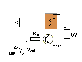
Homework questions:
1. Calculate the resistance of the LDR (Light Dependent Resistor) when Vout is
0.4v.
When light shines on the LDR, its resistance reduces and the voltage
across it decreases. When the voltage across it is 0.4v, the transistor will not
be turned on and we can consider the transistor, relay and Rb to be removed from
the circuit.
This means we have only two components, the 4k3 and LDR forming a voltage
divider.
Here are the things we know: the supply is 5v, the resistor is 4k3, the voltage
across the LDR is 0.4v and the current through the 4k3 and LDR will be the same.
If we work out the current through the resistor, we know the current through the
LDR and the voltage across it is 0.4v.
The voltage across the 4k3 is 5v - 0.4 = 4.6v
The current through the 4k3 = 4.6/4300 = 0.00107Amp
The resistance of the LDR = 0.4/ 0.00107 ohms = 374 ohms
2. Calculate the base current when Vout is 3.2v and Rb is 1k5.
This is where a mistake is introduced.
Before we answer the question, here is the way to look at the circuit.
Remove the LDR and the circuit consists of 4k3, 1k5 and the voltage of 0.6v
across the base-emitter junction.
This means the circuit can be seen as 4k and 1k across a 5v rail.
This means one volt will be dropped across each 1k or resistance.
This means approx 4v will be dropped across the 4k3.
And looking at the 1k5 and base-emitter voltage, the voltage will be about 1.5v
plus 0.6v = 2v.
Now we go back to question 2. The voltage at the join of the 4k3 and 1k5
resistors WILL NEVER be higher than about 2v, so the question is FALSE.
When the LDR is NOT ILLUMINATED, its resistance is very high and we will assume
it is so high that it is equivalent to being removed from the circuit.
This will allow us to work out the maximum current into the base of the
transistor.
Here are the values we use: the voltage across the 4k3 and 1k5 = 5v - 0.6v =
4.4v The total resistance = 4.3 + 1.5 = 5k8
The maximum current is: 4.4 / 5800 = 0.75mA.
If the transistor has a gain of 150, the collector current can be as high as
100mA. This is sufficient to activate a sensitive relay.
Did you spot the mistake in the second question?
The voltage of 3.2v is the voltage ACROSS the 4k3 resistor and NOT the
voltage at the join of the 4k3 and 1k5
The voltage across the 4k3 is determined by:
The total resistance = (4k3 + 1k5) = 5.8v
The voltage across this combination is: 5v - 0.6v = 4.4v
The voltage across the 4k3 = 4.4/5.8 x 4.3 = 3.2v This is the voltage
ACROSS THE RESISTOR.
That's why you must WORK OUTSIDE THE BOX. This means looking at a question in a
very simple way and calculate the approximate values BEFORE using any formulae.
This will prevent you making any silly mistakes and and show-up your instructor
as being HIGHLY INTELLIGENT or ABSOLUTELY STUPID.
![]()
There are three mistakes with this EGG TIMER circuit:
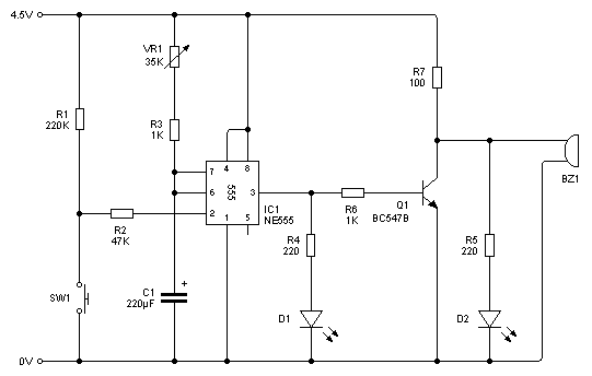
1. What is the purpose of the 47k resistor ?? It can be removed. It
has no function.
2. You will get about 7 to 10 seconds with a 35k and 220u electrolytic. An egg
takes 3inutes to cook !!!!
3. It is a VERY BAD DESIGN to "short-circuit" an output device to turn it off.
This means the LOAD CURRENT is begin wasted via the transistor when the load is
not being driven.
The output transistor is not needed. The buzzer and LED-2 can be connected
between pin 3 and the positive rail. This will save 3 components and produce a
better circuit.
![]()
PUSH PULL
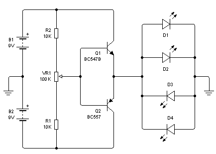
There are no current limiting resistors. The LEDs will be destroyed if the pot is turned fully clockwise. Current-limiting resistors should always be included.
![]()
Look at this twaddle from Professor D.Mohankumar:
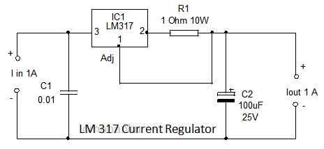
LM317 can be used to make a Current Regulator with constant output current. Figure shows a 1 Ampere current regulator circuit. Here the output voltage is fed back to the adjust pin. That is the low side resistor of the divider is with the load itself. The output current is that resulting from dropping the reference voltage across the resistor.
Apart from the poor English, the electronics expression is appalling. I don't understand what he is talking about.
The whole idea of a constant current circuit is to have an input voltage higher than the output voltage and the input has the capability of delivering a HIGHER current than will be provided at the output.
In the circuit above, the input current is 1amp,so why have a current-limiting circuit????
The current-limiting resistor is 1 ohm. If it passes 1amp, the wattage lost in the resistor will be 1 watt. Why specify 10watt ???
In fact he is entirely wrong in the following:
The value of the output current can be fixed using the formula
Iout = Vref / R1 (this statement is correct)
Suppose we are selecting 10 ohm resistor as R1, then the output current will be
1.25 / 1 = 1.25 Amps.
A 1ohm resistor will produce an output current limited to 1.25 amp. (not 10 ohm)
Practical Electronics for Inventors - hundreds of mistakes!
The discussion on EEV blog:
http://www.eevblog.com/forum/beginners/practical-electronics-for-inventors-3rd/105/
on the text book: Practical Electronics for Inventors
contains corrections on nearly every page of the book and the correction .pdf is almost 150MB in size:
https://onedrive.live.com/redir?resid=967A90CA47FD025B!172&authkey=!ACEbpvA4f9gUlxc&ithint=file%2c.pdf
It surprises me that many of the contributors to the corrections are still in
"awe" of the qualities of this text book.
He goes on to say:
You advertised it as a 555 timer
I never advertised it as a 555 timer.
As one contributor said: It should be JUNKED.
The contributors stated they have had NO SUCCESS in contacting the author with
the corrections.
This does not surprise me.
I have had exactly the same reaction.
That's why I say: you should be able to find almost any text book on the web as
a free download and don't waste any money on any of them.
Read any text book with a lot of suspicion and double check anything you read by
going to other text books and web sites for a clarification or comparison of
confirmation.
I would be EXTREMELY annoyed if I found out statement was incorrect, especially
if I paid for the book.
This website is one of the best on the internet:
http://www.eevblog.com/
and the discussion FORUM can be found here:
http://www.eevblog.com/forum/
The forum is very large and you will find hundreds of valuable contributions.
![]()
I have often mentioned the ineptitude of "Professors" and here's the
latest:
I'm interested in your new TE555-1
IC and would like to know how it works before purchase for my class projects.
Would you please send me the data sheet of this chip and the price break?
Thank you,
Regards,
Heidi Jiao, Ph. D
Professor of Electrical Engineering
Padnos College of Engineering and Computing
Grand Valley State University
616-331-6844
He could see from the circuit that none of the pins correspond to the 555 timer
and the circuit performs completely differently to any 555 circuit. The number
on the chip is
TE555-1.
It is not shown as LM 555 or NE 555.
It's "Professors" like this that should not be teaching electronics.
They have absolutely no practical understanding of electronics and it's no
wonder the students finish a course with no real understanding AT ALL.
He is Professor of Electrical Engineering. He should
stick to electrical wiring.
Another "Professor" produced a video of a single transistor amplifier driving a
speaker.
He failed to clearly mention how the current into the base was amplified by the
transistor to drive the speaker.
I commented about this omission and was banned from making any more comments.
Not only do these "Professors" fail to describe the most important part of the
exercise, but block anyone highlighting their ineptitude.
Another "Professor" said the base-emitter voltage can be as high as 3v for an
NPN transistor !!!!
I pointed this out, as well as numerous other faults on his website and he
immediately closed down the site.
Fortunately, no more Indian students could get hold of the RUBBISH he was
presenting on his site.
This is just a few of the nonsensical comments made by teachers who have never
actually tested any of the circuits they put on the web or consider they may
have made a mistake.
They become quite indignant when someone pulls them up and takes them to task
about the validity of the material they have produced.
![]()
Here is another faulty circuit from Professor D.Mohankumar.
It is supposed to let you know if the earth is connected or not connected at the wall socket.
He states:
The circuit uses the potential difference across the Neutral and Earth lines. Neutral-to-earth voltage as measured at the load for a single-phase circuit is a function of the load current and the impedance of the neutral wire. Various standards limit this voltage drop in a branch circuit to 3% (5% per cent total for feeder and branch circuit) for a reasonable efficiency of operation. Based on this, the neutral-to-earth voltage limit for a single-phase 120V AC circuit is 3.6V AC and for a single-phase 230V AC circuit 6.6V AC.
This part of his reasoning is correct. The voltage-drop in house wiring should be as small as possible and in modern wiring the drop will be less than 1 volt in the active line and 1 volt in the neutral line.
However this voltage-drop only occurs when the load is say 2,000 watts and you cannot detect this drop without a load.
The following circuit will NOT detect any problem with the earth wire, even if you connect a load to the system as any voltage-drop in the neutral wire will make the neutral wire slightly HIGHER in voltage than the earth wire.
This circuit will NEVER work and is a dangerous circuit as it produces a FALSE READING.
This circuit was presented in ELECTRONICS FOR YOU Magazine, without ever being tested.
![]()
![]()
Page 1
Page 2
Page 3
Page 4
Page 5
Page 6
Page 7
Page 8
Page 9
Page 10
Page 11
Page 12
Page 13
Page 14
Page 15
Page 16
Page 17
Page 18
Page 19
Page 20
Page 21
Page 22
Page 24
Page 25
Page 26
Page 27