|
There are many 4x4 Keypads on the market (including eBay) and some of them
are less than $3.00
This makes them idea for inclusion in a project.
The only problem is interfacing them.
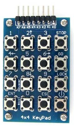
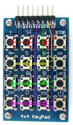
Almost all keypads have a "row and column" connection to the switches and
this produces 8 lines.
If you are using a microcontroller with lots of in/out lines, you can
directly connect the keypad to the micro.
But if you have a limited number of in-out lines, you need to devise a
clever way to reduce the number of interface lines.
The cleverest interface can be done with a single line.
It uses a capacitor and a ladder of resistors to generate a "time delay" and
the timing generates the correct key.
To get the timing correct, the value of the resistors and capacitor must be
the same as the prototype we have produced because the program has pre-set
time-delay values.
Resistor-values are very close to the specified value but capacitor-values
can be 20% higher or lower. That's why the capacitor you use must be tested
before-hand with a capacitance meter to make sure it is very close to 1n.
The circuit and program works like this:
The keypad is looked-at on a regular basis via a loop in the program and the
input-output line is taken HIGH to charge the 1n capacitor. It is then
turned into an input and after a delay of a few milliseconds, the line is
looked-at to see if it is still HIGH. If a switch is pressed, the capacitor
will have been discharged.
The program now knows if a switch is pressed, so the capacitor is charged
again and looked-at every few microseconds to determine how long it takes to
discharge.
The micro exits the sub-routine with the key-value.
We have also provided a separate "test-routine" that blinks a LED to
indicate the number of the key. The LED flashes 5 times for key-5 etc.
Once you get the keypad working, you can add the sub-routine to your project
by "copy-and-paste."
There are many different keypads on the market and we have included photos
and prices of some from eBay, where the prices are the lowest and postage is
FREE.
Ebay gives you a guarantee of quality (and receiving the item) and
purchasing on eBay is only a few clicks of the mouse. It is the
fastest, most-convenient and cheapest way to buy things.
Switch 16 has a resistance of 47k, switch 15 has a resistance of 47k + 12k,
switch 14 has a resistance of 47k + 12k + 12k, switch 13 has a resistance of 47k + 12k
+ 12k + 12k, switch 12 has a resistance of 47k + 47k etc.
You can see each switch has an increased resistance of either 12k or 11k.
This resistance adds to the time to discharge the 1n capacitor and the
sub-routine exits with the correct key.
INSTRUCTIONS TO SET
THE KEY-VALUES
Turn the project OFF.
Push key16 and keep pressed.
Turn ON project.
Release key16.
Push key1 - LED will flash briefly
Push key2 to key16.
Push key1 and LED will flash slowly.
Turn project OFF. Key-values are now in EEPROM.
Turn Project ON. Push key1 and LED will flash once. |
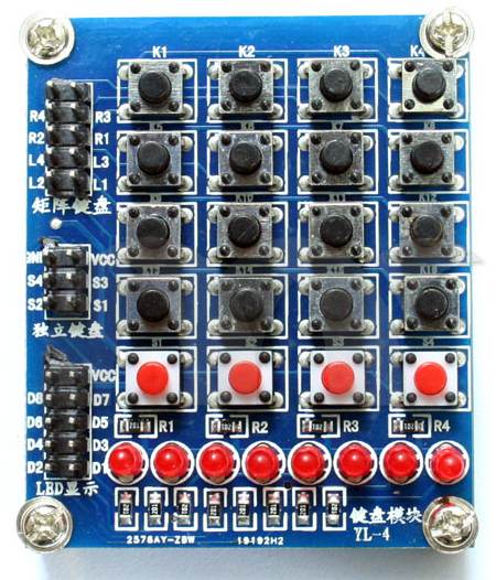
Here are two more 4x4 keypads:
Here is another 4x4 keypad with extra 4 red buttons that connect
directly to the middle set of pins for extra functions in your
project, plus a set of 8 LEDs that connect to the bottom set of
pins. These LEDs can be used to indicate up to 8 different
HIGH's from your project.
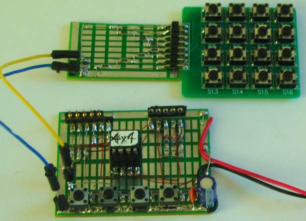
Testing the 4x4 Keyboard on an "Experimental Board"
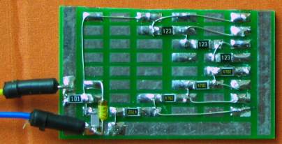
Close-up of the surface-mount components
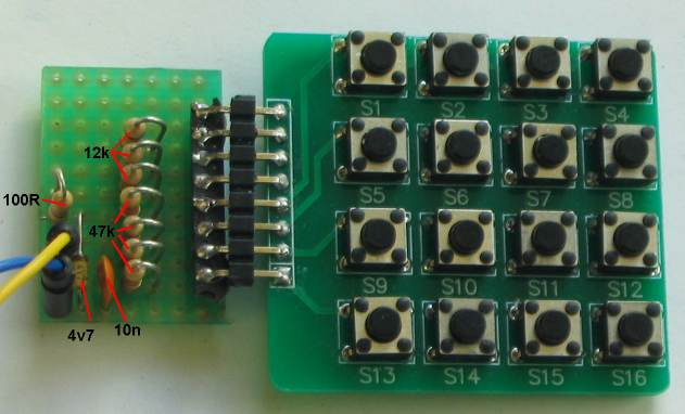
The Interface board using through-hole components
To prove the effectiveness of automatically
creating key-values, we made an interface board with
through-hole components and a 1n capacitor. The detection worked
perfectly.
Many keypad routines have been described on the web using a PIC
based development system called BASIC STAMP, Arduino and
others using programming languages (including C) but none have
added the feature of automatically detecting the key-values and
that's why this program is so reliable. You can change the
interface board and the program will still produce accurate
results. Apart from that, we have shown how it is done. There is
no mystery with hidden instructions and no high-level language
to read and understand. You can take the instructions and add
them to your own program to produce a more-complex design.
The output for the 16 keys, 4 red LEDs and 8 LEDs:
 THE PROGRAM
The program detects key16 first as it takes the shortest time
to discharge the 1n capacitor.
When the program comes to detecting key 1, any slight increase or decrease in the value of the capacitor will be
multiplied 16 times and key 1 will not be detected. That's why the capacitor
must be exactly 1,000p (1n).
Another way to explain the problem is this:
You are
looking through a hole in a wall that is 16 bricks from the ground. You pile-up 16 bricks from a different suppler
but these bricks
are not quite the same. When it comes to the 16th brick, the pile
is less than the bricks in the wall.
Let's explain it a bit more accurately.
The program detects key1 after about 40 loops of a 6uS delay when using our
1n capacitor, but if a 1n capacitor with a slightly higher reading will take
41 or 42 loops.
That's why you need to produce a table of timing values that apply to the
capacitor and resistor-ladder you have selected.
To prevent the keys being incorrectly detected, the program automatically
produces a value for each key from the components you have used, and holds it in EEPROM memory.
These values are download each time the micro is turned ON and loaded into
locations 50h to 5Fh, (at the top-end of the General Purpose Register's
- GPR's).
The program also shows how to access EEPROM for writing and reading.
When the micro is first turned ON, the EEPROM is empty.
To place key-values in EEPROM, press key16 and turn the project ON. The
indicator LED will flash once.
Now press key1 for 0.5 seconds, then key 2, 3, 4, 5 . . . etc to key 16.
Each time the key is pressed and released, the key-value is placed in
a set of temporary files and the indicator LED flashes. After key16, press
key1 and the indicator LED keeps flashing at a low rate.
Now switch the project OFF and ON again. It is now ready to detect the keys.
We have added another "test" routine that will need to be deleted when you add
sub-routines.
The test routine produces flashes to correspond to the key number.
Simply turn the project ON and press key1. The LED will flash once. Push
key16 and it will flash 16 times.
The program is obviously much larger than a simple key-detect routine
because it needs to do a lot of things in the process of creating automatic
key-values.
This program becomes the basis of any project requiring a 4x4 keypad and you
simply add sub-routines to what we have already produced. After adding a few lines of code, give the program
a new name so you can go back to older versions if a mistake is made.
The files:
4x4.asm
4x4.txt
4x4.hex
;*******************************
;4x4 Keypad.asm
;KEYPAD DEMONSTRATION PROGRAM
;Tests 4x4 keypad and flashes LED to indicate key number
;Keypad does not control any devices
;  13-6-2013
;*******************************


	list	p=12F629
	radix	dec
	include	"p12f629.inc"

	errorlevel -302	; Dont complain about BANK 1 Registers during assembly

	__CONFIG _MCLRE_OFF & _CP_OFF & _WDT_OFF & _INTRC_OSC_NOCLKOUT

;_MCLRE_OFF  - master clear must be off for gp3 to work as input pin

;****************************************************************
; variables - names and files
;****************************************************************

	Cblock  20h
temp1	    	;used in delays
temp2		;used in delays
temp3		;used in delays
temp16          ;16 keys
flashes		;LED flashes to indicate key number
loops
SwFlags

        endc

;****************************************************************
;Equates
;****************************************************************
status		equ	0x03
rp1		equ	0x06
rp0		equ	0x05
GPIO 		equ 	0x05


status		equ	03h
option_reg	equ 	81h


	; bits on GPIO

pin7		equ	0	;GP0  LED - flashes to indicate key number
pin6	 	equ	1	;GP1
pin5		equ	2	;GP2
pin4		equ	3	;GP3
pin3		equ	4	;GP4
pin2		equ	5	;GP5  4x4 Keypad switches


	;bits

rp0		equ	5	;bit 5 of the status register


;****************************************************************
;Beginning of program
;****************************************************************
	org	0x00
	nop
	nop
	nop
	nop
	nop
SetUp	bsf	status, rp0 	;Bank 1
       	movlw	b'11001000'	;Set TRIS GP0,1,2,4,5 out   GP3 not used
	movwf	TRISIO
	bcf	status, rp0	;bank 0
	movlw   07h         	;turn off Comparator ports
        movwf   CMCON       	;must be placed in bank 0
	clrf 	GPIO       		;Clear GPIO of junk
	movlw	4Fh             ;start of GPR's
	movwf	fsr
	call    NoKey           ;see if a switch is pressed
	btfss   SwFlags,1       ;test bit1 for switch pressed
	goto    SetUp2          ;load 50h to 5Fh from EEPROM
	call    GenKeyvalue     ;to see if key16 is pressed before start-up.
	movlw   0Ch             ;Put a value into W and perform SUBWF
	subwf   loops,1         ;Carry flag is CLEAR if W is greater than file value
        btfsc   03,c            ;Test carry flag
	goto    SetUp2
	movlw   .16
	movwf   temp16          ;for 16 keys

	call    NoKey           ;test bit1 for switch pressed
	btfsc   SwFlags,1       ;detect no key pressed for debounce
	goto    $-2
	bsf     gpio,0          ;flash LED briefly
	call    _10mS
	bcf     gpio,0
	call    _10mS

	call    NoKey           ;test bit1 for switch pressed
	btfss   SwFlags,1       ;detect key pressed for debounce
	goto    $-2

	call    GenKeyvalue     ;get number of loops

    	incf	fsr,f	        ;fsr starts at file 50h   Store 16 key-values
	movf    loops,w         ;move number of loops into w
	movwf	indf	        ;put loops into file 50h to 5Fh
	decfsz	temp16,f
	goto    $-.15

	call    toEEPROM        ;put 16 values into EEPROM

	bsf     gpio,0          ;added
	call    _500mS
	bcf     gpio,0
	call    _500mS
	goto    $-4            ;keeps flashing - turn off project


         ;load files 50h to 5Fh with key values from EEPROM


SetUp2
	bsf	status,rp0	;select bank1
	clrf	eeadr		;start EEPROM at location 0
	bcf	status,rp0	;select bank0
	movlw   .16
	movwf   temp16      ;for 16 keys
	movlw	4Fh         ;start of GPR's
	movwf	fsr
	incf	fsr,f	    ;fsr starts at file 50h
	bsf	status,rp0
	bsf	EECON1,0	;starts EEPROM read operation storing result in EEDATA
	movf	EEDATA,w	;move read data into w
	bcf	status,rp0
	movwf	indf	    ;put EEPROM data into file 50h to 5Fh
	bsf	status,rp0	;select bank1
	incf	eeadr,1
	bcf		status,rp0	;select bank0
	decfsz	temp16,f
	goto	$-.10
	goto    Main


;********************************
;* Delays 			*
;********************************

_uS     goto	$+1
_uS_1   goto	$+1
        goto	$+1
        retlw   00


_1mS	movlw   80h
        movwf   temp1
	nop
	decfsz 	temp1,f
        goto 	$-2
	retlw 	00


_10mS	movlw	0Ah
	movwf	temp2
_10	nop
	decfsz 	temp1,f
	goto 	_10
	decfsz 	temp2,f
	goto 	_10
	retlw 	00


_100mS	movlw	.100
	movwf	temp2
_100	nop
	decfsz 	temp1,f
	goto 	_100
	decfsz 	temp2,f
	goto 	_100
	retlw 	00


_500mS	movlw   5
	movwf   temp3
	call	_100mS
	decfsz  temp3,1
	goto    $-2
	retlw   00

;****************************************
;* Sub Routines 			*
;****************************************


        ;detect key16 at start-up to generate key-loops for storage in EEPROM
	;this sub-routine also detects a pressed-key and
	;returns with a value in "loops"

GenKeyvalue
	clrf    loops
	bsf	status, rp0 	;Bank 1
	bcf 	TRISIO,5	;clear bit GPIO,5 as output to charge cap.
	bcf	status, rp0	;bank 0
	bsf	gpio,5		;make pin2 HIGH to charge cap.
	call	_10mS           ;charge cap
	bsf	status, rp0 	;Bank 1
       	bsf 	TRISIO,5	;set TRIS GP0,5 to detect discharged cap
	bcf	status, rp0	;bank 0
	call	_uS
	incf    loops,1
	btfsc   gpio,5
	goto	$-3
	retlw   00              ;return with value in loops

	;NoKey - detect no key pressed


NoKey	bcf     SwFlags,1
	bsf	status, rp0 	;Bank 1	 (see if switch is pressed)
	bcf 	TRISIO,5	;clear bit GPIO,5 as output to charge cap.
	bcf	status, rp0	;bank 0
	bsf	gpio,5		;make pin2 HIGH to charge cap.
	call	_10mS           ;charge cap
	bsf	status, rp0 	;Bank 1
       	bsf 	TRISIO,5	;set TRIS GP0,5 to detect discharged cap
	bcf	status, rp0	;bank 0
	call	_1mS
	btfsc   gpio,5
        retlw	00		;no switch pressed
        bsf     SwFlags,1
	retlw	00	        ;key pressed - bsf SwFlags,1


	;ShowKey shows the key value via LED flashes
ShowKey
	bsf     gpio,0          ;
	call    _500mS
	bcf     gpio,0
	call    _500mS
	decfsz  flashes,1
	goto    $-5            ;
	goto    Main


	;TestKeys is a test routine that flashes the key number

TestKeys
        clrf   loops
	clrf   flashes
	incf   flashes,1
	call   GenKeyvalue
	movf   loops,w   ;
	xorwf  50h,w
	btfsc   03,z
	goto   ShowKey
	incf   flashes,1
	movf   loops,w   ;
	xorwf  51h,w
	btfsc   03,z
	goto   ShowKey
	incf   flashes,1
	movf   loops,w   ;
	xorwf  52h,w
	btfsc   03,z
	goto   ShowKey
	incf   flashes,1
	movf   loops,w   ;
	xorwf  53h,w
	btfsc   03,z
	goto   ShowKey
	incf   flashes,1
	movf   loops,w   ;
	xorwf  54h,w
	btfsc   03,z
	goto   ShowKey
	incf   flashes,1
	movf   loops,w   ;
	xorwf  55h,w
	btfsc   03,z
	goto   ShowKey
	incf   flashes,1
	movf   loops,w   ;
	xorwf  56h,w
	btfsc   03,z
	goto   ShowKey
	incf   flashes,1
	movf   loops,w   ;
	xorwf  57h,w
	btfsc   03,z
	goto   ShowKey
	incf   flashes,1
	movf   loops,w   ;
	xorwf  58h,w
	btfsc   03,z
	goto   ShowKey
	incf   flashes,1
	movf   loops,w   ;
	xorwf  59h,w
	btfsc   03,z
	goto   ShowKey
	incf   flashes,1
	movf   loops,w   ;
	xorwf  5Ah,w
	btfsc   03,z
	goto   ShowKey
	incf   flashes,1
	movf   loops,w   ;
	xorwf  5Bh,w
	btfsc   03,z
	goto   ShowKey
	incf   flashes,1
	movf   loops,w   ;
	xorwf  5Ch,w
	btfsc   03,z
	goto   ShowKey
	incf   flashes,1
	movf   loops,w   ;
	xorwf  5Dh,w
	btfsc   03,z
	goto   ShowKey
	incf   flashes,1
	movf   loops,w   ;
	xorwf  5Eh,w
	btfsc   03,z
	goto   ShowKey
	incf   flashes,1
	movf   loops,w   ;
	xorwf  5Fh,w
	btfsc   03,z
	goto   ShowKey
	retlw  00


	;after 16 keys  . . . .
	;put number of loops in 50h to 5Fh into EEPROM


toEEPROM
	bsf	status,rp0	;select bank1
	clrf	eeadr		;start EEPROM at location 0
	bcf	status,rp0	;select bank0
	movlw   .16
	movwf   temp16      ;for 16 keys
	movlw	4Fh         ;start of GPR's
	movwf	fsr
	incf	fsr,f	    ;fsr starts at file 50h
	movf	indf,w	    ;retrieve data in file 50h to5Fh
	bsf	status,rp0	;select bank1
	movwf	eedata		;
	bcf	status,rp0	;select bank0
	call 	write
	bsf	status,rp0	;select bank1
	incf	eeadr,1
	bcf	status,rp0	;select bank0
	decfsz	temp16,f
	goto	$-10
	retlw   00


write	bsf	status,rp0	;select bank1
	bsf	eecon1,wren	;enable write
	movlw	55h 		;unlock codes
	movwf	eecon2
	movlw	0aah
	movwf	eecon2
	bsf	eecon1,wr	;write begins
	bcf	status,rp0	;select bank0
writeA	btfss	pir1,eeif	;wait for write to complete
	goto	writeA
	bcf	pir1,eeif
	bsf	status,rp0	;select bank1
	bcf	eecon1,wren	;disable other writes
	bcf	status,rp0	;select bank0
	retlw	00


;************************
;* Main 		*
;************************

Main
	call   TestKeys
	goto   Main


	END
|
For the next project in this series, using the 4x4 KeyPad, go to:
KeyPadController
ooo00000oooo
11-7-2013
|