| 


   | 


 MISTAKES 
   
 
      Page 19 
 
      
 INDEX 


 The fastest way to learn is from your own mistakes. But up to now, you
 may not have done any PIC programming and so we will have to show you some that
 were generated recently.  
  
  
 1.
 
 One of the biggest mistakes when creating a program is making an output line HIGH but failing to make
 it an OUTPUT. 
 If a line not made an OUTPUT, it will not go HIGH when the bit is set
 (made "1"). 
 The requirement is to make "line 0" an output.  
  
 Here is the faulty code:
 
  
     | 
 
    SetUp   | 
    MOVLW 0D | 
    ;0000 
      1101 | 


     | 
      | 
 
    TRISB | 
 
      | 
   
  
     | 
      | 
 
    GOTO Start | 
 
      | 
   
  
     | 
      | 
      | 
      | 
   
  
     | 
 
    Start | 
    BSF 06,0 | 
 
      | 
   
  
 The value 0D does not make the lowest line an output - it makes it an INPUT! 
 Here is the correct code:
  
  
     | 
 
    SetUp   | 
    MOVLW 0E | 
    ;0000 
      1110 | 


     | 
      | 
 
    TRISB | 
 
      | 
   
  
     | 
      | 
 
    GOTO Start | 
 
      | 
   
  
     | 
      | 
      | 
      | 
   
  
     | 
 
    Start | 
    BSF 06,0 | 
 
      | 


 2.
 Another mistake is referring to the wrong bit in a file. The  bits are
 referred to as bit0, bit1, bit2, bit3, bit4, bit5, bit6, and bit7. The lowest
 bit is bit0  NOT bit1!  
 In the following code, the programmer thought he made the lowest bit of file  0C
 HIGH, but he made the second lowest bit HIGH:


     | 
       | 
    BSF 0C,1 | 
    ;Set the
      lowest line HIGH | 
   
  
 The correct code is:


     | 
       | 
    BSF 0C,0 | 
    ;Set the
      lowest line HIGH | 


  3. 
 Another oversight is forgetting line GP3 for a PIC12c508A is input only.
 
 The instruction above will have no effect. An output device (such as LED or
 speaker) should not be connected to line GP3. It will not be activated. 
  
 
 4.
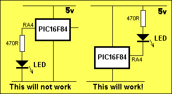
 Line RA4 of a PIC16F84 will only  sink a current. It  does not deliver a current.
 The diagrams below show how a LED can be connected to RA4. The LED in diagram 2
 will illuminate
 when a LOW is output on RA4. 


     | 
    SetUp   | 
    MOVLW 2F | 
    ;0010 
      1111 | 
   
  
     | 
      | 
    TRISA | 
    ;Make RA4
      output | 


     | 
      | 
    GOTO Start | 
      | 
   
  
     | 
      | 
      | 
      | 
   
  
     | 
    Start | 
    
 
  BCF 05,4
   | 
    
 
  ;Make RA4 LOW
   | 
   
  
 5.
 The DECFSZ instruction decrements a file and skips the next instruction in the
 program when
 the file is zero. If we use file 0C, the result of the decrementing must be
 placed in the file. In other words file 0C will be ONE LESS after the
 operation. If the wrong destination is used, the file will not get decremented to zero. In the following delay routine the programmer used the
 wrong destination. (0 = the result of an operation is placed in W.  1 =
 the result of an operation is placed in the file itself).


     | 
    Delay1   | 
    
 DECFSZ 0C,0
   | 
    ;DECrement
      file 0C | 


     | 
      | 
    
 GOTO Delay1
  | 
      | 


     | 
      | 
    
 
  RETLW 00
   | 
 
      | 
   
  
 When the micro enters the delay routine above,
 file 0C is decremented but the result is placed in W and 0C remains unchanged!
 The micro will advance to the next line, execute the instruction GOTO Delay1
 and decrement file 0C again. The value of 0C will not change. The micro
 will be stuck in the loop created by these two instructions and NEVER
 emerge! 
 The correct instructions are:


     | 
    Delay1   | 
    
 DECFSZ 0C,1 | 
    ;DECrement
      file 0C | 


     | 
      | 
    
 GOTO Delay1
  | 
      | 


     | 
      | 
    
 
  RETLW 00
   | 
 
      | 
   
  
 6.
 The following routine will not work:  Why? 


     | 
    Delay1   | 
    
 DECFSZ 0C,1 | 
    ;DECrement
      file 0C | 


     | 
      | 
    NOP | 
      | 
   
  
     | 
      | 
    
 GOTO Delay1
  | 
      | 


     | 
      | 
    
 
  RETLW 00
   | 
 
      | 
   
  
 In the delay routine above, the micro will NEVER
 reach the RETLW 00 instruction. The micro will advance to the NOP instruction
 and when file 0C is zero, the micro will jump to GOTO Delay1 and loop the 3
 instructions again.  
 The instruction after a DECFSZ must be able to answer the following question: 
               
 The file is NOT zero 
 and go to another location. (such as Delay1) 
 The next instruction answers the question: 
               
 The file is ZERO 
 and returns to the routine that called the Delay routine. (or maybe
 continues with further instructions.) 
  
 This is the correct layout for the sub-routine:


     | 
    Delay1   | 
    
 DECFSZ 0C,1 | 
      | 


     | 
      | 
    GOTO Delay1 | 
    ;The
      file is NOT zero | 


     | 
      | 
    RETLW 00 | 
    ;The
      file is ZERO | 
   
  
 7.
 Comparing two files to see if they are the same can be done with the XOR
 instruction. The value in one file is put into W and the following instruction
 is executed:


     | 
 
       | 
    
 XORWF 0C,0
 
   | 
    
  
    ;XOR W
      with file 0C (result in W)
  
   | 


 If the two files are the same, a bit in the status file will be
 turned into a "1". Let's not worry about the name of the
 "bit" because this will confuse you.  
 We now look at the "bit" and see if it is "set". If it is
 "set", the two files are the SAME. 


     | 
  
       | 
    BTFSC 03,2 | 
    
  
    ;Look
      at bit 2 in the status flag
   | 
   
  
 We now create two instructions below BTFSC 03,2:


     | 
       | 
    BTFSC 03,2 | 
    ;Look at bit 2
      in the status flag | 


     | 
      | 
    GOTO xxxx | 
    ;The
      bit is NOT zero | 


     | 
      | 
    GOTO yyyy | 
    ;The
      bit is ZERO | 
   
  
 Name the 2 faults with the following set of
 instructions:


     | 
      | 
    MOVF 0B,1 | 
    ;Copy file 0B
      into W | 
   
  
     | 
      | 
    
 XORWF 0C,0
 
     | 
    ;XOR W with
      file 0C (result in W) | 
   
  
     | 
       | 
    BTFSS 03,2 | 
    ;Look at bit 2
      in the status flag | 


     | 
      | 
    GOTO xxxx | 
    ;The
      bit is NOT zero | 


     | 
      | 
    GOTO yyyy | 
    ;The
      bit is ZERO | 
   
  
 A: MOVF 0B,1 will not copy the contents of file
 0B into W - it only moves the contents in and out of file 0B and sets the zero
 flag. 
 A: The comments: The bit is NOT zero and
 The bit is ZERO are around the wrong way for the BTFSS 03,2
 instruction.  
  
 The correct instructions/comments are:


     | 
      | 
    MOVF 0B,0 | 
    ;Copy file 0B
      into W | 
   
  
     | 
      | 
    
 XORWF 0C,0
 
     | 
    ;XOR W with
      file 0C (result in W) | 
   
  
     | 
       | 
    BTFSS 03,2 | 
    ;Look at bit 2
      in the status flag | 


     | 
      | 
    GOTO xxxx | 
    ;The
      bit is  zero | 


     | 
      | 
    GOTO yyyy | 
    ;The
      bit is NOT ZERO | 


 NEXT   


        |