|
CURRENT TRIP |
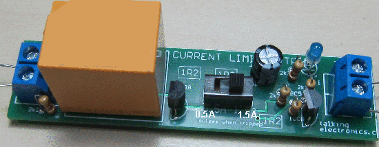
This overload module is very cleverly designed.
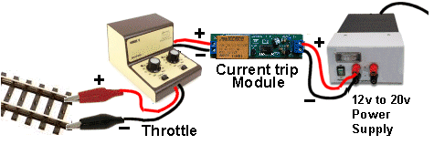
The CURRENT TRIP module is fitted between the Power
Supply and Controller (throttle).
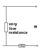
To see how the circuit works, you just look at 2
components. These are two resistors in series:
When you have two very low value resistances in series,
a high current will flow when a supply voltage is
present.
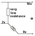
When a current flows, a voltage will be developed across
each resistor.
When a short circuit occurs, point A on the diagram has
a voltage on it.
The only thing that matters is the voltage generated
across the 1R2 resistor. This is the voltage that "turns
the transistor ON." In other words, it saturates
it. It changes from OFF to ON.
The relay starts to “chatter” when the “set
current” has been reached and a short-circuit will only allow the
“set current” to flow. This lets the operator clear the fault and
protect the power supply.

It does no “trip” or shut off the power but limits the
current to the track and produces chatter from the relay to indicate
the "set current" has been reached.
The module costs $12.00 usd and is available from Talking Electronics.
Email Colin Mitchell for more
details.
Here is the circuit: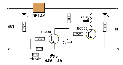
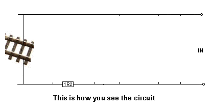
The value of voltage is not important but the important
point to note is the 0v rail has a voltage on it, on the
left part of the rail, as show in the diagram above.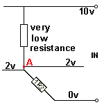
This is called the "Detecting Point" and we connect the
base of a transistor to this point.
When the voltage at Point A rises to 0.6v, the
transistor is activated.
A 2k2 resistor between the Detecting Point and the base
allows the voltage to increase higher than 0.7v without
damaging the transistor. The value of this resistor is
not important. It can be from 100R to 4k7 or higher. 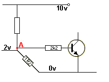
This is what we call a "strong action" or "strong
reaction" and it controls the next stage in the circuit.
You can see the left part of 0v rail rises to a higher
voltage and this triggers the circuit.
The two components in the "detecting circuit" have a
very low value of resistance and this is called a LOW
IMPEDANCE STAGE.
This means a HIGH CURRENT must flow for the detection to
occur.
The switch simply introduces more DETECTING RESISTORS
that reduce the resistance of the detection so that a
higher current is needed for the detection to occur.
Three resistors in parallel create 0.4R and this means
the minimum current will be slightly more than 1 amp.