|
Fixing Electrical Tools |
As an electrician you will
often be called to fix an electrical appliance.
People think an electrician can fix almost anything electrical,
including appliances with speed controls and all sorts of electronic
modules.
Most of the problems are broking leads and wires within the
appliance and this chapter deals with simple repairs.
It is not worthwhile replacing triacs and modules as the problem may be
in the motor and the new module will just block up again.
The first thing you must consider is SAFETY.
You are dealing with a high wattage tool and 240v supply.
You don't know if the tool is earthed or "live." or "shorted" or "open."
and measuring resistance values will not provide much information as a
motor produces a back voltage and its DC resistance is no indication of
the operating current.
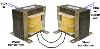
You need an ISOLATING TRANSFORMER to limit the current and prevent
things blowing up on the work-bench.
The simplest and cheapest Isolating Transformer is two identical power transformers
with the secondary wires
connected together. This means the 12v output wires or 24v output wires.
The output voltage MUST be the same.
We are talking about the old-fashioned "E" and "I" laminated
transformer.
It can be from 15 watt to 100 watt. Each 500gm is about 15 watt
capacity and when you connect the primary of the first transformer to
the mains, the primary of the second transformer will produce 240v AC
with a limited current.
This means you can short the output of the second transformer and it
will just "buzz" and not blow a fuse or circuit-breaker.


It will not provide safety from electrocution but it will not blow-up
the tool you are testing.
It is up to you if you want to see the sparks or effect of connecting
the tool to the supply you have created with the two transformers and
you can determine if the to tool works or is open-circuit.
Most tools have an AC motor called a UNIVERSAL MOTOR and the armature is
connected in series with the field winding.
The motor will work on either AC or DC and we will firstly describe how
it works on DC.
You have to know how a permanent-magnet DC motor works. The magnets
provide a North Pole on one side and South Pole on the other.
The armature produces a North Pole on one of the coils on the armature
and this is repelled (pushed away from) the North Pole. One of the other
parts of the armature produces a South Pole and is pushed away from the
south Pole of the permanent magnet.
The motor could be acting in "attract mode" to cause the armature to
rotate. I don't know. And it does not matter.
However it is important to understand the poles of the armature produce
a North Pole during part of the rotation and a South pole during the
remainder of the rotation.
In other words, the poles of the armature are constantly changing from
North to South during each rotation.
Instead of using a permanent magnet, you can wind a coil of wire around
iron laminations to produce a North Pole and South Pole when current
flows through the windings. This is called an electromagnet and the
motor will not know the difference between electrically produced
magnetism and permanent magnetism.
The armature is connected in series with one coil and then in series
with the other coil and the second coil must be connected to produce a
North Pole while the first coil produces a south Pole.
When this is done, the motor will revolve clockwise.
If you reverse the windings to both poles, the motor will revolve
anti-clockwise.
This is called the "set-up".
The two electromagnets are called the FIELD WINDING.
The only way to change the direction of rotation is to change the wires
to both coils at the same time. When you do this, the North pole will
become South.
If you swap the wires to the motor, the armature will continue to turn
in the same direction.
This is because you have reversed the direction of flow of current in
the armature and both electromagnets of the field winding.
In other words you have changed the polarity of the field and the
polarity of the armature at the same time and the same "pushing" or
"pulling" effect will be produced and the armature will continue to
revolves in the same direction.
You have to change both field windings to produce reverse rotation.
If you swap the supply wires very quickly, the motor will continue to
revolves clockwise.
In effect, you have supplied the motor with AC and it has had no effect
on the direction. That's why the motor is called an AC motor or
Universal Motor.
IDENTIFYING THE WIRES
Fortunately, mains cable-colours are RED, BLACK and GREEN/YELLOW and are
easy to follow and understand.
However cables from some tools are BROWN, BLUE and GREEN/YELLOW.
Use the following diagram to match the colours with the colours your are
used to:
