A great kit for self-sufficiency
It's a very simple circuit. The skill in the design is in the transformer.
All the components and PC board: $13.50
0.5v @ 200mA solar cells $2.50 each
0.5v @ 100mA solar cells $1.50 each
Order the kit and/or solar cells from Talking Electronics
These are the pages on SOLAR CHARGERS:
|
1. SOLAR CHARGER
- this page |
![]()
This is another kit in our
self-sufficiency range. We also have a
12v fluoro inverter kit for
those who need to operate 20watt to 40watt fluorescent lamps from a
12v supply.
We will be introducing a number of kits for those who have opted to
live with 12v energy. With nearly everything electronic capable of
operating
from a 12v supply, there is no reason why anyone opting to live with a
low voltage supply cannot enjoy all the electronic pleasures of those
who live in the city.
Some products are not yet available for 12v
operation but inverters are available from 100watts to
4kw.
The aim of this project is to cater for the other end of the range. We are looking at charging a 12v battery, using the cheapest set of solar cells and the cheapest inverter. This also means the cheapest 12v battery - a 1amphr (1AHr) gell cell or 6v cells salvaged from old analogue mobiles!
THE
PROBLEM
The problem with charging a battery from a solar panel is the SUN!
It doesn't shine all the time and clouds get in the way! Our eyes
adjust to the variations in the strength of the sun but a solar panel
behaves differently.
As soon as the sun loses its intensity, the output from a solar panel
drops enormously. No only does the output current fall, but the output
voltage also decreases.
Many of the solar panels drop to below the 13.6v needed to charge a 12v
battery and as soon as this occurs, the charging current drops to ZERO.
This means they become useless as soon as the brightness of the sun
goes away.
Our project cannot work miracles but it will convert voltages as low as
3.5v into 13.6v and keep delivering a current to the battery. Obviously
the current will be much lower than the maximum, when the sun
"half-shines" but the inverter will take advantage of all those
hours of half-sun.
At least you know it will be doing its best ALL THE TIME.
The other advantage of the inverter is the cost of the panel. You don't
have to buy a 12v panel. Almost any panel or set of solar cells will be
suitable. You can even use a faulty 12v panel. Sometimes a 12v panel
becomes damaged or cracked due to sun, rail, heat or shock. If one or
two of the cells do not output a voltage (see below on how to
fix faulty panels) the cells can be removed (or unwired) and the gap
closed up. This will lower the output voltage (in fact it may increase
the voltage - the faulty cells may have reduced the output
to zero) but the inverter will automatically adjust.
The aim of this project is to achieve a 13.6v supply at the lowest cost.
That's why the project has been released as a kit. The equivalent in
made-up form is 3 times more expensive yet doesn't have some of the
features we have incorporated in our kit. We have used a more
efficient output circuit than the closest rival design and the driver
transistor is the latest "low-voltage" type. These two
factors increased the efficiency by 20% over the
rival.
HOW THE CIRCUIT
WORKS
The circuit is a single transistor oscillator called a feedback
oscillator, or more accurately a BLOCKING OSCILLATOR. It has
45
turns on the primary and 15 turns on the feedback winding. There is no
secondary as the primary produces a high voltage during
part of the cycle and this voltage is delivered to the output via a
high-speed diode to produce the output. The output voltage
consists of high voltage spikes and should not be measured without a
load connected to the output. In our case, the load is the battery being charged.
The spikes feed into the battery and our prototype delivered 30mA as a
starting current and as the battery voltage increased, the charging
current dropped to 22mA.
The transistor is turned on via the 1 ohm base resistor. This
causes current to flow in the primary winding and produce magnetic
flux. This flux cuts the turns of the feedback winding and produces a
voltage in the winding that turns the transistor ON more. This
continues until the transistor is fully turned ON and at this point,
the magnetic flux in the core of the transformer is a maximum. But is
is not EXPANDING FLUX. It is STATIONARY FLUX and does not produce
a voltage in the feedback winding. Thus the "turn-on" voltage
from the feedback winding disappears and the transistor turns off
slightly (it has the "turn-on effect of the 1 ohm resistor).
The magnetic flux in the core of the transformer begins to collapse and
this produces a voltage in the feedback winding that is opposite to the
previous voltage. This has the effect of working against the 1 ohm
resistor and turns off the transistor even more.
The transistor continues to turn off until it is fully turned off. At
this point the 1 ohm resistor on the base turns the transistor on and
the cycle begins.
At the same time, another amazing thing occurs.
The collapsing magnetic flux is producing a voltage in the primary
winding. Because the transistor is being turned off during this time,
we can consider it to be removed from the circuit and the winding is
connected to a high-speed diode. The energy produced by the winding is
passed through the diode and appears on the output as a high voltage
spike. This high voltage spike also carries current and thus it
represents ENERGY. This energy is fed into the load and in our
case the load is a battery being charged.
The clever part of the circuit is the high voltage produced. When a
magnetic circuit collapses (the primary winding is wound on a ferrite
rod and this is called a magnetic circuit), the voltage produced in the
winding depends on the QUALITY of the magnetic circuit and the speed at
which it collapses. The voltage can be 5, 10 or even 100 times higher
than the applied voltage and this is why we have used it.
This is just one of the phenomenon's of a magnetic circuit. The
collapsing magnetic flux produces a voltage in each turn of the winding
and the actual voltage depends on how much flux is present and the
speed of the collapse.
The only other two components are the electrolytics.
The 100u across the solar panel is designed to reduce the impedance of
the panel so that the circuit can work as hard as possible.
The circuit is classified as very low impedance. The low impedance
comes from the fact the primary of the transformer is connected
directly across the input during part of the cycle.
The resistance of the primary is only a fraction of an ohm and its
impedance is only a few ohms as proven by the knowledge that it draws
150mA @ 3.2v. If a battery is connected to the circuit, the current is
considerably higher. The 150mA is due to the limitation of the solar
panel.
Ok, so the circuit is low-impedance, what does the 100u across the
panel do?
The circuit requires a very high current for part of the cycle. If the
average current is 150mA, the instantaneous current could be as 300mA
or more. The panel is not capable of delivering this current and so we
have a storage device called an electrolytic to deliver the peaks of
current.
The 10u works in a similar manner. When the feedback winding is
delivering its peak of current, the voltage (and current) will flow out
both ends of the winding. To prevent it flowing out the end near the 1R
resistor, an electrolytic is placed at the end of the winding. The
current will now only flow out the end connected to the base of the
transistor. It tries to flow out the other end but in doing so it has
to charge the electrolytic and this take a long period of time.
These two components improve the efficiency of the circuit
considerably.
You will notice the battery is receiving its charging voltage from the
transformer PLUS the 3.2v from the solar panel. If the battery voltage
is 12.8v (the voltage during charging) the energy from the transformer
will be equivalent to 9.6v/12.8v and the energy from the solar cell
will be equivalent to 3.2v/12.8v. In other words the energy into the
battery will be delivered according to the voltage of each
source.
THE
BLOCKING OSCILLATOR
The operation of the
circuit has been covered above but the term BLOCKING OSCILLATOR
needs more discussion. By simply looking at the circuit you cannot tell
if the oscillator is operating as a sinewave or if it is
turning on and off very quickly.
If the circuit operated as a sinewave, it would not produce a
high-voltage spike and a secondary winding would be needed, having an
appropriate number of turns for the required voltage.
A sinewave design has advantages. It does not produce RF interference
and the output is determined by the number of turns on the secondary.
The disadvantage of a sinewave design is the extra winding and the
extra losses in the driving transistor, since it is turned on and off
fairly slowly, and thus it gets considerably hotter than a blocking
oscillator design.
The factor that indicates the circuit is a blocking oscillator is the
absence of a timing capacitor. The circuit gets its timing from
the inductance of the transformer. It takes time for the current to
start to flow in an inductive circuit, once the voltage has been
applied. In technical terms CURRENT LAGS IN AN INDUCTIVE
CIRCUIT.
The timing feature is hidden in the circuit, but
it has nothing to do with the feedback winding or the transistor. If we
simply place the 45 turn coil (the transformer) across a voltage source,
current will flow in the coil and this will produce magnetic flux. This
flux will cut all the turns of the coil and produce a back-voltage in each
turn that will OPPOSE the applied voltage and reduce the
voltage being applied to the coil. This will cause less current to flow. During
the time when the magnetic flux is increasing (expanding) the current
is also increasing and the full current does not flow until the
magnetic flux is STATIONARY. When this effect is viewed on a set of
voltmeters and ammeters, it appears that the current is LAGGING. In
other words it is taking time to reach full value.
This is the delay that creates the timing for the oscillator.
The voltage generated across the primary winding at the instant WHEN THE TRANSISTOR IS
TURNED OFF, is called a FLYBACK VOLTAGE. The value of this voltage is
determined by the inductance of the transformer (coil), the number of
turns and the strength of the magnetic flux. In our case we are taking
advantage of this energy to charge a battery but if we did not
"tap-off" this energy, it would enter the driver transistor
as a high-voltage spike and possibly damage it. (A reverse-biased diode
can be placed across the winding to absorb this energy).
WHAT?
NO VOLTAGE REGULATION?
Our simple circuit does not
employ voltage regulation. This feature is not needed with a trickle
charger. The charging current is so low the battery will never suffer
from overcharge. To be of any benefit at all, voltage regulation must
be accurately set for the type of battery you are charging. For a 12v
jell cell, it is 14.6v. For a 12v Nicad battery, it is 12.85.
This is the way it works: When a battery is charging, its voltage rises
a small amount ABOVE the normal voltage of the battery. This is called a
"floating charge" or "floating voltage" and is due
to the chemical reaction within the cells, including the fact that
bubbles are produced. When the battery gets to the stage of NEARLY
FULLY CHARGED, the voltage rises even further and this rise is
detected by a circuit to shut-down the charger.
A voltage regulated charger is supposed to have the same results. When
the voltage across the battery rises to it fully charged state, the
output voltage does not rise above this and
thus no current is delivered.
Ideal in theory but in practice the voltage must be very accurately
maintained. If its not absolutely accurate, the whole
concept will not work.
In our case we don't need it as the charging current is below the
"14 hour rate" and the battery is capable of
withstanding a very small trickle current.
PARALLEL OR SERIES?
One of the questions you will be asking is: Should be solar cells be
connected in parallel or series?
Most individual solar cells are made from small pieces of solar
material connected together and placed under a light-intensifying
plastic cover. The output of the solar cells used in the prototype were
0.5v and 200mA (with bright sunlight). The circuit has a minimum
operating voltage of about 1.5v so any voltage above this will produce
an output. In our case the cells should be connected in series to get
the best efficiency.
REPAIRING FAULTY SOLAR PANELS
You may have a solar panel
or individual solar cells and need to know if they are operating
correctly.
All you need is bright sunlight and a place where the entire panel can
be exposed to uniform sunlight.
The main problem is being able to access each of the cells with the
leads of a multimeter while the panel is exposed to sunlight. To
measure the efficiency of each cell, the panel must be delivering its
energy to a load. You can place a switch on one of the lines and
measure across the switch (when it is open) to determine the current
being delivered.
The cells in our prototype measure 3cm x 5cm and deliver 150 mA with
full sunlight. Smaller cells (2cm x 4cm) deliver 70mA.
When the cells are delivering their full rated output current, the
voltage produced by each cell is about 0.4v to 0.45v Any cell producing
less than 0.35v is faulty.
If the output current of your cells or panel is known, (read the
specifications on the panel) you can check
the output by measuring across the switch, as mentioned above. If the
output is considerably less than this, you can short-circuit each cell
in turn to see if the output current of the whole panel increases. The problem is made
more difficult if two or more cells are faulty. Checking the voltage
produced by each cell will detect two or more faulty cells in an array.
If you cannot get to the wiring between each of the cells, you can sometimes get to
the
wiring at the opposite end of the panel by cutting into the backing.
This way you can check the left and right sections separately and
work out if one side is operating better than the other. From there you
can cut into one side of the panel and maybe get 75% of the panel
operational. 75% of a panel is better than 100% of a dead panel.
This project is especially designed for a low-voltage panel. If you
have a panel slightly below par, it is better to buy a few extra cells
and increase the voltage so the panel can be connected directly to the
battery. This way you will deliver 100% of the output to
the battery. Our inverter has a maximum efficiency of 75%, so a panel
that produces nearly 13.6v should have a couple of extra cells fitted
so it can be connected directly to a battery.
9v
to 12v OUTPUT
If you require 9v to 12v
output, you will need to add the four voltage-regulating components
shown in the diagram below.
With the voltage-regulation components added, the circuit produces a 9v
or 12v output. This arrangement is only suitable if you
have a constant, reliable, source of sun as any clouds will reduce the
output to below the regulated voltage. (If a 9v1 zener diode is
fitted, the output voltage will be 9v.) The BC 547 prevents the
ZXT 851 oscillator transistor turning on when the voltage is slightly
above 12v (or 9v). The 10u on the output stores the "reference
voltage" and keeps the BC 547 turned on during the time when the output voltage is above 12v.
This effectively stops the oscillator, but as soon as the output voltage drops
below 12v, the circuit comes back into operation,
"charge-pumping" the 10u on the output.
The 12v zener works like this: No voltage appears on the anode end (the
end connected to the 100R resistor) until 12v is on the cathode. Any
voltage above 12v appears on the anode and this voltage passes through
the 100R to the base of the BC 547. For instance, if 12.5v is on the
cathode, 0.5v will appear on the anode. When the base sees 0.7v, the
transistor turns on, so slightly more than 12.7v is needed to turn on
the transistor.
The regulation components are not really necessary as a reliable output
will only be present when strong sunlight is seen by the solar panel. For the cost of a rechargeable battery or set of
rechargeable cells, you get a much more reliable arrangement by
removing the regulation components, using the first circuit in the
article, and allowing the battery to deliver the 9v or
12v. The battery appears as a HUGE electrolytic on the output,
delivering a constant voltage and is capable of delivering a high
current.
OUR
PROTOTYPE
Our prototype consisted of
8 solar cells charging two 6v batteries in series. These were obtained
from old analogue phones and were purchased for $5.00 each but if you
want to spend a lot more, you can get individual AA cells or a 12v jell
cell.
The solar cells in our prototype are rated at 0.5v and 200mA
The array produced 3.2v @ 150mA with bright sunlight and the output of
the inverter was 12.8v @ 31mA during the initial charging period.
This reduced to 22mA as the battery became charged. As more cells are
added, the charging current increased.
WINDING
THE TRANSFORMER
The primary winding
consists of 45 turns of 0.25mm wire on a 10mm dia ferrite rod. Twist the two ends together to keep the coil in
position.
The feedback winding must also be wound in the same direction if you
want to keep track of the start and finish as shown in the circuit
diagram. It consists of 15 turns spiral wound so that it takes 8 turns across the rod and 7 turns back to the start. Twist the two ends
together to keep the coil in position.
The result is called a transformer. It's a feedback or blocking
oscillator transformer with a flyback feature. The output is taken
across the primary via a high-speed diode.
The oscillator will only work when the feedback winding is connected
around the correct way. The correct way is shown in the diagram, with
the start of the primary and secondary as shown in the diagram. For
this to work, both windings must be wound in the same direction.
You can keep track of the start and finish of each winding or
simply connect the transformer and see if it works. If it doesn't work,
reverse the feedback winding (reverse only one winding - NOT
both).
Nothing can be damaged by trying this method as the solar panel does
not deliver enough current to damage the transistor.
CONSTRUCTION
Wind the transformer as explained above and have it ready for fitting
to the PC board. Fit the other components according to the overlay on
the board making sure the transistor and diode are around the correct
way. The two electrolytics must also be fitted around the correct
way.
Now comes the transformer. As we have already mentioned, the easiest way
to fit the transformer is to solder it in position and try the circuit.
If it is around the wrong way, the circuit will not produce an
output. Reverse one of the windings and the job's done.
| PARTS
LIST 1 - 220R 1/2 resistor 1 - 470R 1 - 1k 1 - BC 338 transistor 1 - BY 207 or equiv high-speed diode 1 - 10u 16v electrolytic 1 - 100u 25v electrolytic 2m - 0.25mm enamelled wire 1 - 10mm dia ferrite rod 5cm long 1- Solar Charger PC Board Regulation components (not in kit) 1 - 100R 1 - 10u electrolytic 1 - 9v or 12v zener diode 1 - BC 547 transistor |
TESTING
THE CIRCUIT Order the
kit and/or solar cells from Talking Electronics
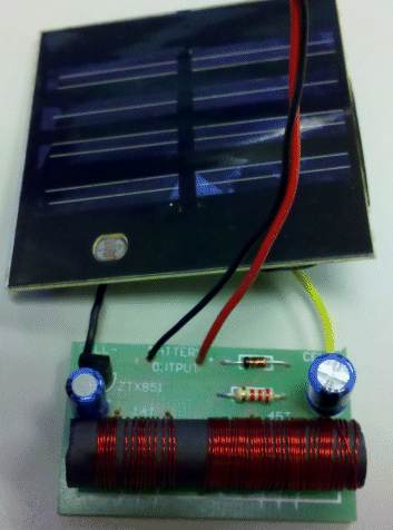
Here is a completed kit from a reader. He has connected a very small
solar panel to the circuit and the output is very small. You can see each
cell on the solar panel is very small and this type of panel is not
suitable. The output from these type of cells is only 25-35mA. The cells we sell are 100mA and 200mA and this is the
minimum output current for this type of circuit. Each cell produces about
0.6v, no matter how large it is and the intensity of the sun.
Here is a YouTube video of the circuit on breadboard:
The output current of the
project can be measured with a multimeter set to milliamps. Place
the meter between the battery and output of the circuit as shown in the
diagram below. You can add an electrolytic to the output to smooth the
pulses to get a more-accurate reading. Select a scale such as 0-100mA
(for analogue multimeters) or 0-199mA (for digital multimeters). Note
how the multimeter is connected, with the positive lead to the output
of the circuit and negative to the battery.
There are many ways to "visualise" how the meter should be
connected. The best way to remember is this: think of the meter as
going directly across the output, to measure the current. Which way
would it be placed? Obviously, the positive of the meter to the output
and negative to ground. But you must NEVER place an amp-meter
(ammeter) (or milliamp-meter) directly across the output of a supply as this will
either damage the supply or the meter. So, include a resistor (or in
our case, the battery being charged), and you will measure the
"current flowing."
Do not
measure the voltage without a load. The output voltage will be as high
as the transistor will allow. This will be as high as the rating of
the transistor. In other words it will be as high as the "zener
voltage" of the transistor (the collector-to-emitter voltage-rating
of the transistor).
You may not be able to measure the output of the circuit accurately
with a high impedance (digital) multimeter. One constructor got a
reading of 1900v from a digital meter. This is obviously incorrect
and was due to the high frequency of the circuit interfering with
the reading.

You can now see how the
circuit works. It generates a voltage higher than the battery voltage
and that's how it can deliver energy to the battery. The energy comes
in the form of "pulses" and we can measure the
"average" or "equivalent to DC value" on a milliamp
meter (a multimeter set to milliamps).
A
FEW NOTES ON TRANSFORMERS
Transformers are one of the
versatile components in electronics. They can be large, small,
high-frequency, low-frequency, single winding, multi-winding, step-up
or step-down (voltage) high-current, isolating, extremely-high voltage,
voltage-reversing or even a combination of any of the above. They can
be technically very complex, or very simple to design and you could
spend a life-time studying their construction.
On the other hand you can learn how to construct them very quickly.
Simply copy a design and maybe modify it a little. By copying a design
you "home-in" on the essential features such as wire-size,
core size, number of turns etc and you can change any of the features
to suit your own requirements.
Before we start, let's point out the two main mis-conceptions of a
transformer. Firstly, a transformer only operates on a voltage that
turns on and off. This is commonly called AC (it stands for Alternating
Current but this also means the voltage is ALTERNATING). The voltage
can also be a DC voltage that turns on and off - commonly called
chopped DC.
A battery cannot be connected directly to a transformer. It will not
work. An oscillator (an oscillator circuit) is needed to convert the DC
into pulses.
Secondly, the energy into a transformer (called watts) is equal to the
watts output of the transformer (minus some losses). If a transformer
on 240v AC (or 110v) produces 240 AMPS output, the output voltage
must be low because the maximum input wattage for 240v is 2400 watts.
This means the maximum output voltage is 2400/240 = 10 volts. Even
though a transformer performs amazing things, it abides by the laws of
physics. In general terms, if an output voltage is higher than the
input voltage, the current will be lower.
https://www.youtube.com/watch?v=c_erzmvVIqI&feature=youtu.be
![]()
7-5-2016