SPOT
Page 1
Page 2
Page 3
Page 4
Page 5
Page 6
Page 7
Page 8
Page 9
BATTERY CHARGER FAULTS
The transformer will produce 15v x 1.4 = 21v - 0.6v = 20.4v
Here is another battery charger with the battery connected directly across the
power-supply:
Another faulty circuit:
From these circuits you can see problem.
This circuit has a current-limiting 6 ohm resistor. This value is not a standard
value and maybe you can use 2 x 3R3 3watt resistors in series. The 1N4001 diodes
limit the current to about 1 amp (or slightly more) and when this current is
flowing, the 6R resistor will drop 6 volts. This resistor is very important to
limit the current and prevent damage to the circuit.
Why will (does) a battery-charger transformer BURN OUT?
More faulty designs from Electronics For You magazine:
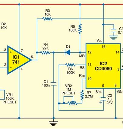
The supply is 12v and the reset line (pin12) needs to see a voltage below 3v for
a guaranteed reset. The LOW of ICI (pin 6) will be about 0.5v and diode D1 will
drop 0.7v. The voltage divider made up of the 100k and 22k will drop 2.5v. This
gives a total of 3.7v. This will not guarantee a reset for the CD 4060
chip. Just another bad design.
Another faulty design from Electronics For You magazine:
The 47k base resistor will allow 0.2mA to flow into the base. If the transistor
has a gain of 100, the collector current will be 19mA. If the gain is 200, the
collector current will be less than 40mA.
Another faulty design from Electronics For You magazine:
CD4093 is a NAND Schmitt Trigger. It has not bee drawn correctly. The input of a
Schmitt Trigger needs to see about 65% or more of rail voltage to guarantee a
HIGH input.
An over-designed circuit from Electronics For You magazine:
What is the point in using a chip to produce 50mA current-limiting when the
whole circuit could be created with a single transistor and three components:
You never mention VOLTAGE when talking about a CONSTANT-CURRENT circuit. That's
because the supply-voltage must always be HIGHER than the voltage required by
the device being supplied the current and the supply-voltage can be MUCH HIGHER
than required as the excess voltage will appear across the transistor and lost
as HEAT.
Here are some mistakes from
Professor Vidyasagar
Sir website:Vidyasagar
Sir's Electronics Web. It is clear he does not know what he is talking
about:
Each RC section creates some voltage drop, so it is only suitable for low output
voltage applications.
L is an inductor but if a choke is used the filtering action will be better.
UNTRUE
THE MISTAKES!
Page 18
Page 10
Page 11
Page 12
Page 13
Page 14
Page 15
Page 16
Page 17
Page 19
Page 20
Page 21
![]()
You cannot design a circuit and put it on the web without doing your
homework.
Homework consists of researching the number of circuits that have already been designed; and
testing your circuit for faults, reliability, unnecessary components and current
consumption.
Many designers (especially from
Every components in every position has a range of "design values" that lets the
viewer understand what the component is doing.
If it is outside this range, a qualified engineer will look at the circuit and
try to work out why the particular value has been chosen.
This is a point that has never been discussed in any text book and is one of the
main underlying points behind the SPOT THE MISTAKE articles.
Identifying faults in a circuit has never been done before and this is possibly why
there is such a proliferation of mistakes in magazines and on the web.
There are lots of hidden, technical mistakes that go unchecked and don't show up
until something gets damaged.
Having fixed over 35,000 electronic devices including TVs, amplifiers, etc I
approach every repair with the attitude: why did it fail? how did it fail; and
how to prevent a future failure.
The same applies to every circuit on the web.
Has it been designed correctly?
Are there weak points in the design?
Are there unnecessary components?
With this attitude you have a head-start to designing a fault-free circuit.
I know SPOT THE MISTAKES gets very few readers out of the 5,000 visitors each
day, but over the 25 years of writing articles, I have helped many readers to
achieve great results, and although this may represent only 1 person in 10,000
it is about the recognised percentage for electronics wizards.
You can see a recent email from a reader of Talking
Electronics Magazine who attributes his success to "getting in early,"
reading my articles and "taking it all in."
![]()
There are lots of battery charger circuits on the web and many have major
faults.
It is obvious the authors have not tested them.
Some circuits are so badly designed that the transformer will burn-out or the
battery will dry out in a short period of time.
The main problem is this: It is very difficult to charge a battery.
You simply cannot connect a battery to a transformer and expect it to work.
Batteries have different cut-off voltages (the maximum voltage that can be
applied to the battery before "gassing" occurs) due to the composition of the paste
applied to the lead plates.
Some compositions prevent the cell �gassing� until a higher voltage is reached
during charging and this allow the battery to be classified as �Sealed.� This
means you can fully charge the battery and providing the charging voltage does
not reach this specified voltage, the battery will not produce any gasses. Other
led-acid batteries are ordinary cells and have a lower cut-off (gassing) voltage.
You can detect (monitor) this voltage with a meter or have an electronic circuit detect
the voltage.
There are two ways to charge a battery. Manually or automatically.
An automatic circuit MUST reduce the current to a very small amount (or zero),
then the "gassing voltage" is reached to
prevent the battery DRYING OUT.
If charging a battery manually, it must be disconnected when the "gassing
voltage"
is reached.
You cannot simply connect any transformer to a battery.
A battery-charger transformer is specially designed to produce an output voltage
(after rectification) that is exactly the required voltage. The secondary
winding will be accurate to "half a turn."
In addition, the transformer must be low-impedance so it will deliver a current
right up to the point of �cut-off� and taper the current to almost zero when the
"gassing voltage" is reached.
This is very hard to do without electronic detection circuitry and even 100mA
being delivered to a battery over a long period of time will eventually dry it out.
One other factor to take into consideration is this:
If the battery is being used each night for say illumination, and the battery is
charged each day,
you need to work out if the charging circuit will fully charge the battery in
the remaining hours of the day.
Most chargers work on a 14 hour-rate. The charger delivers 10% of the amp-hr
rate for 14 hours.
Here is the type of faulty battery charger circuit I am talking about:
The battery is just like a zener diode and its maximum voltage will be 15v when
fully charged. This means a voltage of 20v will be delivered to a device
(battery) that has 15v across it. Since there is no current limiting device
between the two voltages, a very high current will flow and this current could
be high enough to burn out the transformer or the diodes.
No current limiting resistor between the transformer and battery means an
unknown high current will flow.
Some of the circuits will turn off when the battery voltage reaches a maximum
value, but the transformer may already be overheated. 
Connecting a transformer to a battery is a very risky (dangerous) thing to do.
A battery is just like a zener diode. If you supply a voltage just below the
value of a zener, no current will flow. If you increase the voltage to the exact
value of the zener, a current will flow. If you increase the voltage slightly, a
lot more current will flow. That's why you need a resistor between the supply
and the zener. The resistor will limit the current.
The same with a battery connected to a transformer. If the output voltage of the
transformer is slightly higher than the voltage of the battery a high current
will flow. The exact amount of current will depend on the construction of the
transformer and the thickness of the wire in the secondary winding.
Because the size of the current is unknown, you need a current-limiting resistor
and an ammeter to check the current. There is no formula because we don't
know the number of turns on the secondary, the turns on the primary, the type of
material in the core or any of the other factors.
However you can consider the transformer is driving into a short-circuit. Just
like a 5v transformer driving into zero ohms, a 20v transformer driving into a
15v battery will deliver more current than expected and overheat the
transformer. ![]()
![]()
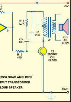
But when the transistor is driving an inductive load such as an audio
transformer, the gain of the transistor is considerably LESS.
The audio transformer is classified as 1k:8ohms. This means the primary has an
impedance of 1,000 ohms at about 400 to 800 cycles. In other words the primary
appears as a 1k resistor. But the actual resistance of the primary will be only
about 100 ohms and because it appears as such an unknown value of "resistance"
the gain of the transistor will be considerably less than 200 or even 100.
The gain of the transistor will be 100-200 when the collector current is about
1mA to 10mA, but when the current is increased to 50mA to 100mA, the gain drops
considerably. For this circuit the gain of the transistor will be no more than
70. But to get the transistor to drive a current though the primary of the audio
transformer requires the transistor to be drive harder than expected. This means
the base resistor must be in the order of 2k2 to 4k7.![]()
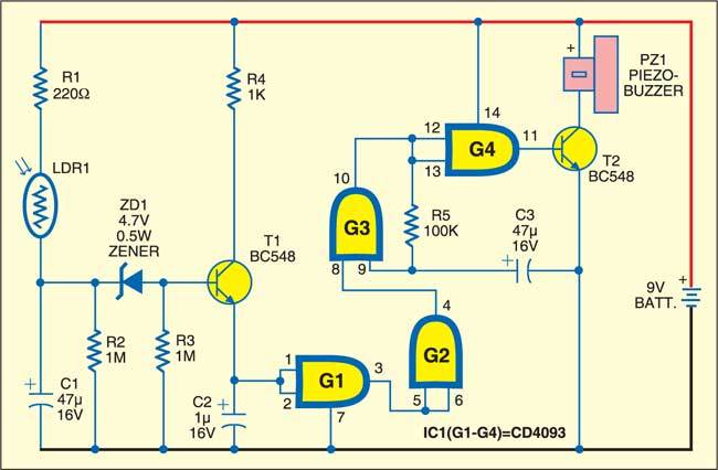
Pins 1,2 will see less than 65% and the circuit will not work.
The voltage across the zener will be about 4.7v and the drop across the
base-emitter junction of T1 will be 0.65v, making a total of 5.25v. This
produces less than 50% for the input of the gate. Another bad design. ![]()
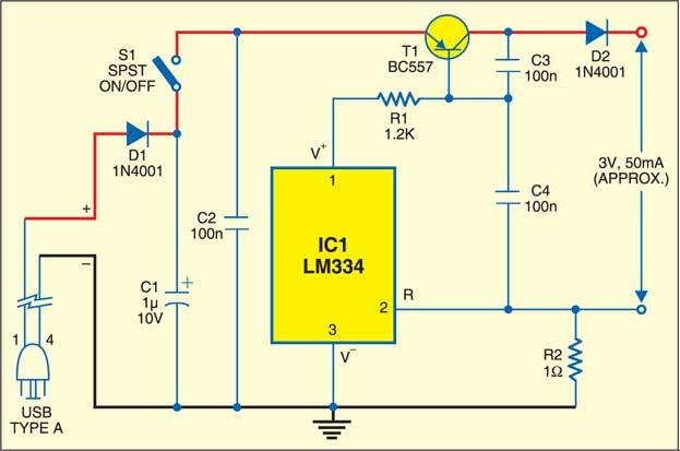
Not only is the original circuit far too complex but the mention of 3v is
inaccurate and has no relevance to the output as the actual voltage will depend
on the number of cells being charged. ![]()
This is UNTRUE It is only suitable for LOW CURRENT applications as the
current creates the voltage-drop across each section. 
An Inductor and choke are the same thing.
Current flow is continuous - What does this mean ????
The transformer can be used very efficiently - What does
this mean ????
The filtering action of the circuit is independent of load current -
what RUBBISH. ALL filtering networks create a larger ripple when
the current increases.
In this circuit, an inductor is connected in series with a load resistor. The
inductor opposes any variation in the current flowing through it. Thus, when a
changing current from the output of the rectifier circuit flows through the
inductor, a back e.m.f. is produced across the inductor. This prevents the
variations in load current. This circuit is suitable for low voltage and high
current. UNTRUE. It is suitable for any voltage.
The above explanation is very hard to follow.
Here is clear definition.
Suppose the current though the inductor is pure DC. Very little voltage will be
dropped across the inductor because it has a very low resistance. But it will
have a very slight voltage across it that is slightly more-positive on the input
terminal.
But if the current increases, the expanding lines of magnetic flux will cut each
of the turns in the inductor and create a voltage that adds to the existing
voltage. Suppose the voltage from the rectifier increases. This will increase
the voltage through the inductor and the inductor will create an increased
voltage to oppose the incoming voltage and thus the increased current will not
flow. And the voltage on the input will rise. We call this a "back e.m.f."
because it is coming out of the inductor to oppose the change in current.
![]()
Here's how NOT to design a circuit:
When the switch is released, the BC547 turns ON via the 100k and the
collector-emitter current turns ON the BC557. This activates the relay and
60mA flows through the coil. This current flows through the base-emitter
junction of the BC557. A transistor is not designed to pass this amount of
current via the base.
The BC557 turns ON and since the collector is connected to the base of the
BC547, both transistors are turned ON in a LATCH arrangement. However the 60mA
flows through the base-emitter junction of the BC547 and this is not a good
design.
There is no need to have a latching arrangement. The application only needs a
single transistor to operate the relay with a 3k3 base resistor:
![]()
Here's a totally absurd question from Earl Boysen and Harry Kybett's book for beginners: COMPLETE ELECTRONICS SELF-TEACHING GUIDE with Projects:
The diode in the circuit shown in Figure 2.25 is known to break down at 100
volts, and it can safely pass 1 ampere without overheating. Find the resistance
in this circuit that would limit the current to 1 ampere.
When the diode breaks down with 100v across it, the wattage dissipated in the
diode will be 100 WATTS!
How could Earl Boysen and Harry Kybett allow a stupid question like
this to appear in their beginners book??
The Voltage Divider is covered in the text book but no mention is made that the
output voltage will drop when it delivers a current to a LOAD. The beginner will
get the impression that it is ideal for supplying a voltage and current.
It is the worst arrangement for supplying a current to a LOAD. This arrangement
is wasteful, inefficient and rarely used. 3-terminal regulators and Switch-Mode
Power Supplies have taken over from voltage dividers.
The text states:
The object of this circuit is to create an output voltage that you can
control. This
statement suggests the circuit is a good design. This is FAR from the truth.
Here's another absurd experiment:
How can you adjust a 1M pot to a value such as 10k or less? This is an absolutely impossible task. It shows that Earl Boysen and Harry Kybett have no practical electronics experience AT ALL.
The book highlights the need to turn OFF the transistor with a base resistor connected to 0v rail:
The 1M resistor is NOT NEEDED. The base can be left floating. Only a microscopic current will leak into the base and allow much less than 1 microamp to flow in the collector-emitter circuit. If the transistor is DC coupled to another stage, a current of less than 1 microamp will flow in the collector-emitter circuit of the second transistor. This sort of complexity need not be explained to beginners.
The text book goes on to cover biasing the base via two resistors. It does not explain WHY this is done:
There is no point in adding the lower resistor. It does not change the fact that the circuit is impossible to analyse.
Look at the following diagram. What a stupid way to draw a circuit. Convention ALWAYS says to draw a battery with the negative at the bottom to create the 0v rail. This is the sort of rubbish they are foisting on beginners. The book should be BANNED!!!
Then they ask a stupid question like: Which way do the currents circulate? -
clockwise or anticlockwise?
The current circulates according to how the circuit is drawn!!!!
Here is a bad example:
A lamp takes six times more current to get it to turn ON because the resistance of the filament is much lower when it is cold. If the lamp resistance is 240 ohms when cold, it will be over 1k when hot. So the example is a disaster. This fact is not mentioned in the text book. Wait until the beginner gets into the REAL world and finds the circuits he has been shown DO NOT WORK !
The text book spends far too much time on the Common Emitter stage as shown in the following diagram:
The circuit above is NOT a practical circuit because transistors have a gain of 50 to 100 or
even 200 and the collector voltage will be much higher or lower than the expected
mid-rail voltage. The book discusses this type of circuit in lots of detail, then goes on to talk about the bridge-biasing stage
and all the previous discussion is wasted.
It does not cover the self-biased stage at all and it is really a disastrous text
book. Such a lot is omitted and such a lot of unnecessary questions are
included.
The author's understanding of how a transistor behaves at the point of saturation
is far from reality and gives the beginner a false understanding. The authors
concepts are so bad I cannot begin to work them out.
All I can say is this: to get a transistor to saturate (when about 100mA
collector-current is flowing), takes up to 10 times more current than you
expect. This is because the gain of the transistor drops considerably when the
current is above 1mA to 10mA. The gain-figures used in the examples apply to a
collector current of 1mA to 10mA. In addition, to get the transistor to
fully turn-ON, requires EVEN MORE BASE CURRENT. These facts are not covered in
the text book and that's why it is such a disaster.
Transistor DO NOT conform to tight tolerances like resistors. They are not 5%
higher or lower when sorting through a batch. They are 50% lower and up to
200% higher. You cannot begin to put them into a stage that does not have any
self-biasing features. The book is really a cruel joke for beginners.
Here's another fault:
transistors with the same part number have � values within a narrow range of
each other.
Untrue. BC547A = 110 to 220
BC547B = 200 to 450
BC547C = 420 to 800
BC547 = 110 to 800
All these have a range of +100% The author's don't know what they
are talking about.
Here's another mistake: For example, suppose a transistor has 500mA of
collector current flowing, and you
know it has a � value of 100. Almost NO transistor has a � value of 100
for 500mA collector-current. The gain drops to 25 when 500mA flows. The author's
are out of touch with reality.
Here's another disaster:
The value of � will be almost the
same for all measured values of collector-current. This demonstrates that � is a
constant for a transistor. UNTRUE.
The gain of a transistor reduces ENORMOUSLY as the collector-current increases.
In most data sheets the gain of a transistor is given for 1mA to 10mA. These are
totally misleading values. When the current increases to 100mA or more, the gain
drops by 50% to 90%.
Here is the same mistake again: It is a property of
the transistor that the ratio of collector current to base current is constant.
If you connect a capacitor and resistor in series (as shown in Figure 6.3), the circuit functions as a voltage divider. This may be so, but that's not the reason why a capacitor and resistor are connected in series. And we don't describe this as a "Voltage Divider:"
There are so many facts omitted from the text book. Take the
following example. The book does not mention the fact that a coil and
capacitor in parallel is called a TANK CIRCUIT and the waveform produced
by the combination can produce a waveform that is 10 times larger than the
supply voltage. It can be even higher (50 times).
Here is the absurd wording:
Because of the low DC resistance of the coil, the DC voltage at the collector is
usually close to the supply voltage (Vs).
In addition, the AC output voltage positive peaks can exceed the DC level of the
supply voltage. With large AC output, the positive peaks can actually reach 2Vs,
as shown in Figure 9.10.
It is obvious the writers do not understand the capability of the circuit AT
ALL.
Here's an absurd sentence:
An inductor is a coil of wire, usually wound many times around a piece of soft iron. In some cases, the wire is wound around a non-conducting material.Does it mean magnetic NON-CONDUCTING or electrical NON-CONDUCTING ??
Let's look at this totally impractical circuit:
The zener must be able to handle the wattage is the globe burns out. If it burns
out, the voltage across the zener will be 20v. The current through the 7R5
resistor will be 30v/7.5 = 4 amps.
The wattage of the zener must be 4 x 20 = 80 watts. The cost of an
80 watt zener is $???? 80 watt zener NOT AVAILABLE.!!!
This is the sort of RUBBISH they are teaching beginners !!!!
The text book is analysing the following circuit to produce a voltage-divider.
In 40 years I have never used a resistor, capacitor and inductor to produce a
voltage-divider.
I have never seen this type of circuit used as a voltage divider.
I don't know where he gets his ideas from.
It's no wonder a beginner will be confused. He is being taught things he
will never use.
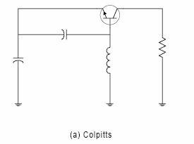
The
TANK CIRCUIT
One of the most important concepts of electronics is the TANK CIRCUIT. This is
because two simple components, a coil of wire - called an inductor - and a
capacitor will produce a waveform (a sinewave) when a pulse of energy is
delivered to the parallel combination. But that's not the amazing part. The
amplitude of the sinewave can be LARGER than the applied voltage. In other
words, the two components will AMPLIFY the pulse and produce a beautiful result.
When this was discovered, RADIO was born.
It is very complex to understand and the text-book does not describe it
properly.
You need to understand how the circuit works because it does two things that are
amazing.
Firstly it produces an output voltage that can be 10 times or more than
50 times larger than the applied voltage and secondly the output voltage
will be REVERSE POLARITY to the applied voltage.
Firstly you need to supply a pulse of energy to the parallel combination. This
is the first secret to describing how the circuit works. Don't keep the switch
pressed for too long because the circuit only needs a very short pulse of
energy.
When you deliver this pulse, the flow of energy into the inductor will produce
magnetic flux and this will cut the turns of the coil to produce a back voltage
(called a back emf) that will oppose the incoming voltage and only allow a small
amount of energy to pass through the coil.
However the capacitor will be uncharged and it will readily accept all the rest
of the pulse of energy.
The switch is now released and the capacitor will be fully charged and it does
not matter if we have delivered too much energy to the coil or very little
because the circuit will now start to operate.
The voltage on the capacitor will deliver energy to the coil and this will
produce magnetic flux that cuts the turns of the coil to produce a back voltage.
This will limit the flow of energy from the capacitor to the coil and it will
take time (maybe only a few milliseconds or microseconds) for the energy to pass
from the capacitor to the coil. When all or nearly all the energy has passed,
the magnetic flux can no-longer be maintained and it starts to collapse. This
collapsing magnetic flux cuts the turns of the coil in the opposite direction
and produces a voltage in the turns that is opposite to the supplying voltage.
This voltage charges the capacitor in the opposite direction.
And the amazing part is the voltage can be higher than the original voltage.
When all the flux has been converted to electricity, the capacitor begins to
send the charge to the coil and although the voltage is in the opposite
direction, it produces expanding flux and the cycle begins again.
During the cycle, some of the energy will be lost in the magnetic flux and the
following waveforms will be reduced. That's why a small pulse of energy must be
delivered to the circuit to maintain its operation.
These important points are completely missing from the text book and without an
explanation like this, the beginner gets a false understanding of how the
TANK CIRCUIT works.
There are many more faults with the text-book and apart from the fact that
emitter-follower stage is very poorly presented, the main problem with the book
is the lack of simple detail, explaining WHY a circuit is chosen for a
particular application. The author never mentions the output current of an
emitter-follower stage is 100 times (or
� - the gain of the transistor) the current entering the base. He
only talks about the voltage gain of "1."
There are a lot more stupid comments to falsely steer the beginner and it's a
waste of my time going over any more of the pages as the book should be
"shelved."
The book is not worth buying as you can get everything by Googling the web.
In fact, you can get a much better explanation and by visiting a number of
educational sites, you will avoid the faults in the text-book.
I add this to my long list of text books that should be taken off the shelves.
As you would expect, no reply from Wiley, the publishers of the book:
info@wiley.com
A "plastic" reply from Earl Boysen, one of the authors of the book:
earl@buildinggadgets.com
After 2 weeks I received a reply from Wiley:
Thank you again for your errata for the above book. I have been corresponding with the revising author and we will incorporate a few of your suggestions. (A FEW OF YOUR SUGGESTIONS!!!!)
You are certainly entitled to your opinions and we respect them. However, we do feel that disagreements among professionals in many professions occur and we would like to think such disagreements are handled with the utmost respect for all parties involved.
Regards,
Carol.
Harry Kybett has died.
I know no-one likes to be criticised, but when you are taking a huge amount of
money - $34.00 ($17.00 for a second-hand copy) for a few pieces of paper, you have to take responsibility for delivering
something
of value.
It's fortunate you can download nearly every book on the web at no cost
to see the content. Even so, far too many people are buying books, sight unseen,
and regretting their purchase. You can see second-hand copies for 1/10 the price
and this is an indication of the worthlessness of the book.
Before we go, here are more than 10 absurdities, that show the complete lack of
understanding of electronics, of both authors:
The op-amp suggested in the text is OPA134. Cost $3.50
Why not use a simple, cheap op-amp?
The text claims the collector voltage of a TURNED-ON transistor is 0v. This is
UNTRUE.
The text-book uses too many "non-standard" value components. Values I have never
heard-of and never used. This is not the way to educate the beginner.
The text-book describes too many circuits that are not practical and have never
been used in practice. Biasing the base with two resistors and a three
transistor DC coupled circuit are two examples.
The book never covers capacitor values as "n" For instance 100n is 0.1u
All ceramic capacitors are identified as 102, 103, 104.
Many questions are difficult to answer. For instance: "What makes an amplifier
into an oscillator"
Answer: "A resonant LC circuit with feedback of the correct phase and amount."
There are many more answers. It does not need an LC circuit. It just needs
POSITIVE FEEDBACK.
The text book constantly says the reactance of a capacitor should be 1/10 the
resistance of the parallel resistor but does not explain WHY!!!
That's the purpose of a text book.
Many sentences are badly worded. For instance: "Both transformer coils are
usually wound around a core made of a magnetic material such as iron or ferrite
to increase the strength of the magnetic field."
A magnetic core allows a higher flux density (than air) to flow around
the path called the MAGNETIC PATH. The magnetic material does not
increase the strength of the magnetic field, it just allows a higher density
flux to flow though the magnetic path.
Figure 2.32 has the incorrect current-value for the lamp and/or I don't
understand the question.
The text-book specifies a 1N4735A zener? Why not just specify the
zener voltage? We are not trying to sell zeners !!
Here is one of the sentences I do not agree with: "You can consider the diode to
be a perfect diode and thus assume the voltage across it is 0 volts."
A PERFECT DIODE will have 0.7v across it. A faulty diode will have 0v
across it !!!
He then goes on to say that 0.7v is dropped across a diode when the current is
100mA or 1Amp !! In actual fact the voltage increases to about 1.1v when
the current increases and that's why the diode gets hotter and hotter as the
current increases.
A globe is included in some examples. This is a very bad example
as a cold globe has a resistance of 1/6th the hot resistance and many of the circuits
SIMPLY WILL NOT WORK.
The battery symbol is drawn with the negative at the top.
The equations contain mixed units: VR = 1 kΩ x 10 mA = 10 volts
and M
All these things show a total lack of understanding of teaching, especially to beginners.
You have to take a broad-look at the content of the book to see how many of the pages are unsuitable for a beginner and quite irrelevant to the understanding of how a particular building-block works. No mention is made of the self-biased transistor stage and the two simple stages mentioned in the book are a disaster to bias. The book goes into far too much detail with oscillators using inductors and fails to include the "phase-shift oscillator" and multivibrator, the two most popular oscillators and the easiest and cheapest to design.
That's why I am so critical of the book. If you are going to charge for something, make sure it cannot be criticised.
To say: Complete Electronics Self-Teaching Guide with Projects is a complete overstatement. Hardly a project to be seen and nothing about the self-biased transistor, multivibrator or Phase-shift Oscillator - two of the most important - fundamental - building blocks.
We will see what corrections have been done. You can get all the same content on the web AT NO COST. The content is by-far a compete course and it leaves out some very important building blocks.
I was horrified by the reply: "We will incorporate a few of your suggestions."
It took Wiley and Boysen TWO EMAILS to get them to reply and they only replied because of my website and the possible exposure I created.
Overall the book is not worth buying and you can see a BASIC COURSE in ELECTRONICS on our website.
![]()
Here's another stupid project from Electronics For You (September 2013 issue) by D. Mohankumar:
You can always bet he will come up with a worthless circuit, filled with
mistakes.
Firstly, you don't need the op-amp. The circuit below turns ON the transistor
when the solar panel reaches 11.6v
You don't need D3 and some of the other components.
You can't connect a 14v transformer to a 12v battery without a current-limiting
resistor. The transformer will BURN OUT. Resistor Rx (10R) is needed to match
the two components. I have told both
Mohankumar and EFY about this mistake for the past 12 months but the Technical
Editor of EFY Sani Theo has failed to reply and failed to check or test
any of the projects submitted by D. Mohankumar. How can you possibly expect the
Indian electronics beginner to succeed when the major electronics magazine in
India is so inept.
D. Mohankumar must have finally read some of my comments as this is his comment
on his site:
His main hobby is to snap shot my circuit and publishing the same in his website with abusing comments. The comments have been made after emailing D. Mohankumar with NO REPLY. The circuits DO NOT WORK.
He also post such comments in my blog but I am not moderating the same because the language is not suitable for a public site.
He is not testing the circuits before making comment like �will not work�, �don�t do this�, �hazardous design� �poor design�, �rubbish circuit� �disaster� etc. How do you know I am not testing the circuits ???????
I don�t know how one can confirm the working of the circuit without testing. He claims that he can confirm the working through visual observation only. That's the DIFFERENCE between him and me. I am a PROFESSIONAL . I don't put STUPID circuits on the web.
Really, a magic that cannot be done by any experts in electronics. That's where you are WONG. How do you think I have designed circuits for the past 40 years?? I can see them working in my mind and then put them together. He should go to an electronics expert before he makes such STUPID comments. He is making a FOOL of himself.
Here's a comment from another electronics site: One of the most useful skills in electronics is that of looking at a circuit diagram and understanding how the circuit works.
You can "see" aa circuit working if you understand the principles of electronics. D. Mohankumar doesn't understand the basics so he will never be able to see a circuit working.
7,000 visitors read Talking Electronics site each day and anyone can send me an email.
D. Mohankumar hasn't bothered to correct the RUBBISH on his site.
He keeps putting silly things on his website:
All diodes are zener diodes. The picture above is a diode. What does the (+) and (-) mean? Only the cathode (k) lead is marked. The actual placement in a circuit will depend on the type of diode, its function and if the cathode is connected to the 0v rail. Sometimes the anode is connected to the 0v rail. That's why only the "k" lead is identified.
If 334 produces a current of 22mA how can 684 produce a current of 100mA ??
None of the values above make any sense.
In his Capacitor-fed Power Supply, he gets mixed up with voltage and current. He
doesn't understand that a Capacitor-fed Power Supply is a CURRENT DRIVEN supply.
The output voltage depends on the LOAD.
Any capacitor on the front-end can produce a supply from 1v to about 300v.
That's why they are so dangerous.
He says silly things like:
But the limiting resistor R is important, without which the Zener diode will be
destroyed.
The capacitors on the front-end are LIMITING THE CURRENT - not the
resistor in series with the zener. The zener WILL NOT BE DESTROYED.
The volt-dropping resistor (not CURRENT-LIMITING) is designed to allow the
electrolytic to remove the ripple.
A capacitor-fed power supply is COMPLETELY DIFFERENT to an ordinary supply and
he is confusing the two.
He uses a 4 amp fuse to protect 100mA Power Supply !! That's why he knows NOTHING ABOUT ELECTRONICS.
That's why he should GET OFF THE WEB.
If you read an article by Professor D. Mohankumar on Dog Breeding where
he said Pekinese "grow ears out of their mouth, " you would immediately realise
he doesn't know what he is talking about. The same with electronics. Just one
stupid statement and he should be banned from the web. He is hiding behind his
stupidity by not displaying my comments on his website. I have already sent more
than 20 comments and NOT ONE has been displayed.
It's no good "crying on your website" about being treated unfairly when
you have completely abused your responsibility by repeatedly producing false and
misleading information, AFTER reading this article, and being told of the
mistakes.
It's hard enough to learn electronics without some IDIOT coming along and
delivering faulty material.
It's a pity no-one else is correcting theses websites but, as I said, it takes a
lot of understanding to realise they contain faults.
I have criticised over a dozen writers, authors, "electronics professionals"
"electronics professors" and NONE have written to me to say I am wrong.
In most cases they have not even had the decency to fix the mistake.
I have over 4,200,000 visitors in the past 2 years and none have said I am wrong.
Very few people understand the basics of electronics. They can calculate the
impedance from a formulae and do other wondrous, complex things, yet fail to understand the difference between an
ordinary power supply and a capacitor-fed supply.
I am here to teach the BASICS. You can get the advanced theory from a book. It's
the basics that is never explained correctly or skimmed-over because the
explanation is very hard to put into words.
Show me an explanation of the Phase-shift Oscillator - without the non-sensical
approach of saying it consists of three 60� phase-shifts. We know it must have a
total of 180� phase-shift, but HOW DOES THE CIRCUIT WORK? Most books glide
over the real explanation and when you test a circuit and find negative on a
capacitor, you get a surprise.
![]()
Here is a slight correction to a very good tutorial on Inductance at:::
http://www.electronics-tutorials.ws/inductor/inductance.html
The coils should be placed in alignment as the magnetic flux extends out the
ends of the coil and very little is produced along the sides. Placing the coils
side-by-side gives the beginner the wrong impression on how coils are mutually
coupled.
I mentioned this to:
Wayne Storr
webmaster@electronics-tutorials.ws
but no change has been made on the website.
It's small things like this that give the wrong impression and make it
hard for the beginner to learn.
![]()
Here is another Basic Electronics website that is filled with mistakes.
Electronicstheory.com
Two diodes are around the wrong way. The input of the High Pass Filter is
shorted to ground.
The PNP transistor is connected incorrectly. The battery symbols are incorrect.
The inputs to the Schmitt Trigger gates are connected to the outputs.
This will make the gates oscillate at 100MHz for this chip as it is a very
high speed chip.
Here is the reply from Mr Ray Dall:
but I wouldn't expect you to see, much less understand that.
The text also has numerous mistakes.
For example, he states CURRENT flows from NEGATIVE to POSITIVE.
This is the direction of ELECTRON FLOW.
Current Flow is called CONVENTIONAL CURRENT and flows from POSITIVE TO NEGATIVE.
If we don't have a common way to describe current-flow, how are we going to use
Flemings Left and Right Hand Rules????
He also states:
Pin 5 of the 555 sets a "control voltage (typically .6 to .7 volts - typical e-b
junction biasing for a silicon transistor). When pin 6 rises ABOVE the voltage
at pin 5, the timing interval ends. WHAT RUBBISH !!!!!!
He also describes the Multivibrator incorrectly and other things.
The site is written by:
Ray Dall BSEE
Radio Frequency Engineer
comments@electronicstheory.com
I emailed some comments and got this reply:
How can an "electronics engineer" make so many basic electronics mistakes, refuse to identify them, reply with a number of rude emails, then want to "hide under the table."
![]()
Next we have Greg's Basic
Electronics who is trying to flog his Basic Electronics course for $37.00.
 It
might be worth $37.00 if it doesn't contain any of mistakes on his web page and
in his preview eBooks.
It
might be worth $37.00 if it doesn't contain any of mistakes on his web page and
in his preview eBooks.
Here are some of his interpretations of electronics:
1 - 100k linear taper pot.
How can you get "linear taper." It's log taper or antilog taper or
LINEAR.
He states a chip has Vcc and Vcc-
How can you get Vcc- ????
He states capacitors are measured in microfarads and picofarads and forgets nanofarads.
This is because he is from the radio days and not up-to-date with modern electronics.
Don't try driving a large load like big stereo speakers with the LM386. It works great for small
Here's Greg Carpenter
speakers.
What does he mean by this?
Some values to try are .05uF for C1 and C2 as well as 18k for the LM386. That
will make a lower pitched note.
What does he mean by this?
When current flows through an inductor a magnetic is formed around the
inductor. When the current stops the field collapses back. Also, if you take a
magnet and pass it around a coil a current will be induced in that coil or
inductor.
What terrible English-Expression. I know what he is trying to say but a
beginner will get the wrong interpretation.
He is also recommending eBooks by Jestine Yong and these are filled with
poor grammar and its almost impossible to work out what is being taught.
All the data in these eBooks is readily available on the web for FREE and it's
pointless spending money on poorly written technical material.
![]()
Professor D.Mohankumar is still coming up
with RUBBISH articles. Here is his latest disaster.
He claims an 800 VA inverter with 126 Ah battery can power 500 watts load for 3
hours.
To deliver 500 watts requires very close to 50 amps. He claims the battery
voltage is 14.8v when fully charged.
The 14.8v is called a "floating charge" and is the "back voltage" produced by
the battery when it is fully charged. But as soon as you draw a current, the
voltage immediately drops to 12.6v and possibly a little lower when 50 amps is
delivered.
Inverters are not 100% efficient and that's why you can safely allow 50 amps for
a 500 watt load.
At 50 amps you are drawing current on a "2.5 hour basis" and a 126Ahr battery is
rated at 126AHr when current is drawn over a period of 14 hours. At 50amps you
will get less than 100AHr. But at 50 amps the voltage of the battery will drop
to 10v after about 1 hour so the inverter will drop out after 60 minutes and NOT
3 hours.
More RUBBISH from Professor D.Mohankumar:
12v / 0.1A = 120 ohms NOT 120k
1/4watt resistors will accept up to about 500mA if the resistor is 1 ohm or
150mA if the resistor is 10 ohm. Or 125mA if the resistor is 15 ohm and 105mA if
the resistor is 22 ohm.
The current depends on the resistance of the resistor.
Use the formula: Wattage of resistor = (ICurrent x ICurrent
/ Resistance of resistor

Professor D.Mohankumar keeps adding to his
website with articles containing dozens of mistakes. He still does not listen
and refuses to correct his articles.
What does this mean:
Zener diode requires a series resistor to limit current across it
What does this mean:
Instead of the Zener, we can use a 7805 voltage regulator which is more
reliable.
This is another of
Professor D.Mohankumars stupid circuits:
The second zener and the BRIDGE is around the wrong way.
When the voltage rises, the first transistor turns ON and the third transistor
turns ON. This turns OFF the middle transistor and the first transistor does
NOTHING. What is supposed to happen??
Where does he get this RUBBISH from:
The forward voltage drop range in Blue and White it will go up to 5 volts.
LED current minimum 20 mA is required to get sufficient brightness.
Don�t use White or Blue LED as indicators. They consume 3 volts from the
circuit and the light is not healthy for the eyes.
In battery operated devices, it is better to avoid LED to conserve power.
LED is a polarized device so it should be connected in the correct polarity. The
long lead is positive.
The resistor is called a �Ballast Resistor� which protects LED from damage due
to excess current.
It is measured in terms of lumen per watt (lm w).
When will he get off the web ??????
Look what this IDIOT is putting in ELECTRONICS FOR YOU Magazine
October 2013.
Sani Theo, the Technical Editor doesn't check ANYTHING:
When the mains wiring is proper, a potential difference develops between the
neutral (N) and earth (E) lines and transistor T1 turns ON to light up the green
LED (LED1). This indicates that the earth connection is perfect.
The Active and Neutral enter a property via either two separate wires or a screened wire with the ACTIVE in the middle and the NEUTRAL wound around the outside.
These two wires go back to a transformer down the road where the 240v is produced by a transformer. As we know, the secondary of a transformer is not connected to any other wiring and so one of the leads is connected to a wire that runs down the lamp-post to a spike driven into the ground.
This wire becomes the NEUTRAL as it will not have any voltage on it.
The other wire is called the ACTIVE and these two wires go to each home.
At the meter-box, these two wires are connected to each outlet as ACTIVE and NEUTRAL.
But suppose the spike at the lamp-post gets broken.
The two wires will now be "floating" and if you touch the Neutral, you will get a tingle.
For instance, if you have a toaster and the heating element is connected to Active and Neutral, and the metal frame is not connected to anything, you will get a slight tingle if the heating element has a slight leakage to the frame.
This is because all the voltages are "up in the air."
Now we introduce a SAFETY wire. It is called EARTH.
At the front of the house we hammer a long spike into the ground and connect a green lead.
We take this green lead to the earth pin of all the outlets.
This wire is connected to the frame of all appliances.
Now, it does not matter if the Active and Neutral are "up in the air" because the frame of the toaster is SAFE to touch.
But the Active and Neutral are NOT UP IN THE AIR. The neural is connected to the ground via a spike at the lamp-post and if not CALL THE ELECTRICAL SUPPLY.
I have written this so that even PROFESSOR D.Mohankumar can understand how the supply to your house is generated.
What is D2 doing? When the Active reverses, D1 prevents and current-flow
so D2 is not needed.
R4 is not needed as the green LED only turns ON when the earth generates a
fault. The red LED should be green. The green LED should be
red.
![]()
Here's some RUBBISH from Electronic Supply Co. They are trying to sell a Basic Electronics Course for $250.00 and their website is filled with mistakes. Here are a few:
A FET does not turn ON when the gate is "floating"
The arrow is going around the wrong way
The arrows are going around the wrong way. The circuit is flickering too
fast to see what is happening.
The emitter is not connected to 0v. The circuit will never work.
How can you possibly expect to learn anything from a website that has basic faults in their promotional material.?
![]()
Here's some more RUBBISH from an Indian University website:
http://nptel.iitm.ac.in/courses/Webcourse-contents/IIT-ROORKEE/BASIC-ELECTRONICS/
Lecture 24 Cascade Amplifiers:
The base has 10 ohms. The biasing of the second stage will result in the base
voltage being 11.9v How do you expect the transistor to have any
amplitude????
On top of that, the value of Rc (500k) will produce NO output as the output is
provided by the value of the LOAD resistor. This is something we discussed in
The Transistor Amplifier article and have never been mentioned in any text
book. Prof. Pramod Agarwal does not understand what he is
doing. How do you expect the students to understand?
Obviously the base resistor should be 10k and the output 500 ohms. But no student
has picked up the mistake in 6 years!! I wonder how much they are learning
!!!!!
I noticed the mistake IMMEDIATELY because each resistor in a circuit has a range
of values that will be acceptable. If they are outside this range, you need to
look at the circuit and find out WHY?
Here is a bridge rectifier from his website:
He doesn't even have the understanding to look at the diodes and make sure they are all facing towards the positive output.
![]()
Here's another project from Electronics For You (October 2013 issue) with mistakes:
Apart from the fact that the circuit is far too complex, the 10u (C10) can be charged via diode D1 and electrolytic C5. But when transistor T2 turns ON and lowers the voltage on the collector, the 22u drops and D1 is reverse biased and C5 is not discharged. This means C5 gradually charges and never discharges. The circuit will never charge C10 and thus the circuit will not work.
Just another untested RUBBISH circuit presented by Sani Theo (the technical editor) of Electronics For You.
![]()
Page 1
Page 2
Page 3
Page 4
Page 5
Page 6
Page 7
Page 8
Page 9
Page 10
Page 11
Page 12
Page 13
Page 14
Page 15
Page 16
Page 17
Page 19
Page 20
Page 21