|
|

Note: All the circuits described in this article must be used for experimental purposes only and must not be used for any illegal activity.
These circuits are very powerful, in that they are very hard to detect and will pick-up the slightest whisper and transmit the information 3km and more. Because of this, government laws are very strict and will come down very heavily on any mis-use.
The purpose of this article is to compare different circuits and explain the features that contribute to a good design. Some of these circuits (the best of each design) are available from Talking Electronics in kit-form and/or ready assembled. See the Talking Electronics website for the list of kits and devices.
JUST OUT! |
|
Get this handy data
ebook |
FM TRANSMITTERS
The first group of circuits we will discuss are FM TRANSMITTERS. They
can be called SPY TRANSMITTERS, FM BUGS, or a number of
other interesting names. They all do the same thing. They transmit on
the FM band in the range 88MHz to 108MHz.
Most of them can be adjusted to transmit above or below the band and you
need a radio that will pick up these frequencies, to detect them.
Since the FM band is almost entirely filled with radio stations, we will
be providing details on how to adjust a radio so it will scan EITHER
above the band or below the band. Most radios can only be adjusted 10MHz
above or below but this will be enough to provide a "blank" space for
your transmitter.
FM transmission provides perfect quality and when one of these
transmitters is used in a house and received on a good quality radio,
you cannot tell if the person is actually talking in the next room or
via an FM link, through a radio.
This means all the FM bugs have the same perfect audio, but some
circuits will detect fainter sounds and others will transmit further.
Some circuits can be handled without drifting off-frequency and others
are designed to be very small or fit on top of a 9v battery.
By building these circuits you will learn an enormous amount about high
frequency, audio and getting the maximum output with the least current.
This is the main aim of this article. It will add a number of "building
blocks" to your understanding of electronics.
Before I start, there are two things that particularly annoy me. The
first is a circuit diagram with C1, R1 etc and a parts list identifying
the values. Circuit diagrams like this are obviously drawn by a non-electronics
person. The whole concept of looking at a circuit diagram and seeing the
values gives the reader an indication of how each section will work. A
section may be operating very lightly with high value components or it
may be working very hard with low value components. The whole idea of
providing a circuit diagram with marked components is to give the reader an immediate
understanding of how the circuit is operating.
The second thing that annoys me is the labelling of parts
on a PC board as R1, C1 etc.
Again, the board has been designed by a non-technical person.
Why design a board without component values? Do they think the
values will change? How can you assemble a board without referring to a
circuit diagram?
The whole purpose of well-designed PC board is to build it without referring to any other data.
Keep this in mind when designed your own boards.
Also, don't name your boards "A51/834-2." Give then a name you can
remember or one that refers to the application it will perform.
Let's start:
1 TRANSISTOR CIRCUITS
There are a number of 1 transistor FM transistors on the market in
kit-form and already assembled.
These circuits are interesting to look at but do not really perform very
well.
1. They do not have a good transmitting range.
2. They do not detect low-level sound, and
3. They do not operate very well on 1.5v. No transmitter can be expected
to operate very well on 1.5v. If you want to use a single cell, use
a lithium cell as it produces 3v.
4. Some have a coil etched on the PC board. No FM transmitter will
perform very well with a coil etched on the board.
Why use 1.5v?????
Transistors do not operate very well below 0.9v and the collector load
resistor needs a small voltage so it can perform its task (the same
applies to an emitter resistor) and thus the lowest voltage for a circuit
is 1.5v. If only a single cells is used, there is no allowance for a
voltage-drop as the cell becomes depleted. Always use 3v as the lowest
supply voltage.
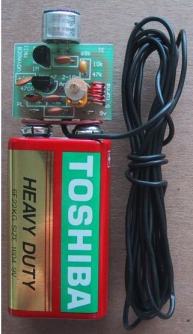
THE SIMPLEST CIRCUIT
The following circuit is the simplest FM circuit you can get. It has no
microphone but the coil is so MICROPHONIC that it will pick up noises in
the room via vibrations on a table.
The circuit does not have any section that determines the frequency. In
the next circuit and all those that follow, the section that determines
the frequency of operation is called the TUNED CIRCUIT or TANK CIRCUIT
and consists of a coil and capacitor. The transistor and components
surrounding the tuned circuit simply keep the tuned circuit operating at
its RESONANT FREQUENCY. This circuit does not have this feature. The
transistor turns on via the 47k and this puts a pulse through the 15
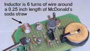
turn winding. The magnetic flux from this winding passes through the 6
turn winding and into the base of the transistor via the 22n capacitor.
This pulse is amplified by the transistor and the circuit is kept
active.
The frequency is determined by the 6 turn coil. By moving
the turns together, the frequency will decrease. The circuit
transmits at 90MHz. It has a very poor range and consumes 16mA.
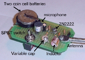
THE SIMPLEST BUG
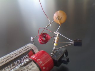
The components soldered to the 2 cells
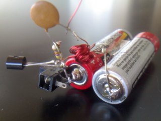
Rear view of the simplest bug
After making a transmitter, you will want to know if it is
transmitting. In the case above, the circuit will only produce a carrier
and this will be heard on the radio as a "quiet spot."
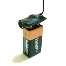
Rather than chasing up and down the dial, Talking Electronics has
produced a piece of test equipment to let you know the bug is
transmitting and the approx frequency of transmission.
It is called
FIELD STRENGTH METER MkII.
The photo below shows the Field Strength Meter near the bug. The plastic
knob on the trimmer allows adjustment without affecting the detecting
circuit. Simply turn the knob (with the two antennas
near each other) and the 3 LEDs on the project will illuminate.
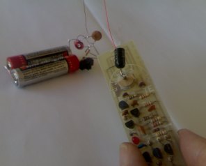
Field Strength Meter and Bug
So far we have seen an unstable circuit in action. Placing a finger
near the bug will change the frequency. This is totally unsuitable.
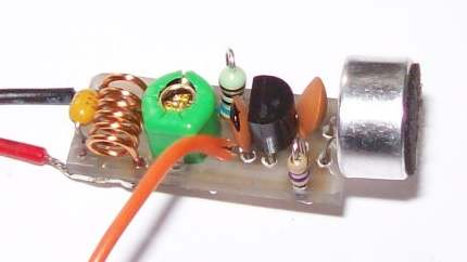
A ONE TRANSISTOR CIRCUIT
The next circuit uses a TUNED CIRCUIT or TANK CIRCUIT to create the
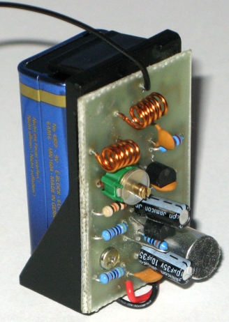
operating frequency. This is clearly shown in the diagram. For best
performance the circuit should be built on a PC board with all
components fitted close to each other. The photo below shows the circuit
using a coil etched on the board. This type of coil is totally
unsuitable. It does not have a high "Q" and the range is very
poor. The board cannot be touched as the capacitance of your body
causes the circuit to drift. A wound coil will improve the stability
considerably. See photos below for the details of a wound coil.
A one transistor
circuit
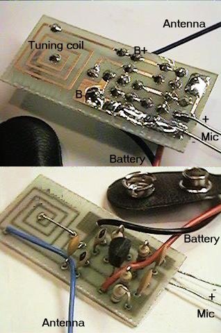
Here is the 1-transistor circuit produced by Darren Dazaro on a home-made PC board and heat-shrunk so the air-trimmer is adjustable via a small hole.
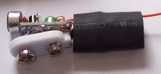
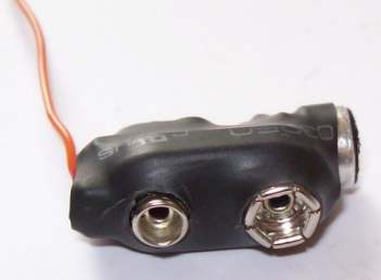
and a cut-out for the air trimmer
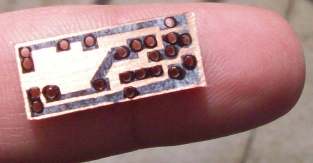
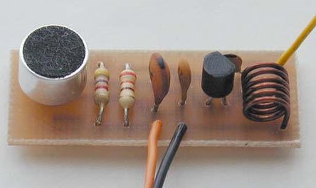
BAD LAYOUT
Here is
Firstly the coil and capacitor should be near each other. The coil should not have long leads. and a 22n capacitor should be across the supply to give the circuit better performance. The value of C2 is too high. It should be 10p. The coil should be 5 turns. The electret mic should not be connected directly to the base of the transistor. As you can see, the circuit is full of faults.
You can learn a lot from other people's mistakes.
![]()
![]()
A BAD DESIGN
This circuit is completely different to all the other designs in this
section. It is a common-emitter design, whereas all the circuit we are
presenting are common-base designs. The circuit has not been tested and
you can build it and compare the output with some of our designs.
Two mistakes on the circuit are:
The top 10n is not needed as the emitter is held rigid by the lower 10n.
10p on the base does nothing.
![]()
Before we go to an improved design, here is an unusual circuit using a PNP (BC 557) transistor. Firstly, PNP transistors do not work as well as NPN transistors. I would reverse the 4k7 and electret mic as the voltage between base and 0v rail is very small and the 4k7 is not biasing the transistor - it is not needed! The range will be 50 to 100 metres and the current is about 3mA.
Note: A reader built this circuit. It did not work!!
Try putting the 47p across the coil. The 33p may need to be reduced to 10p.
It is just a BAD design, but a good challenge to see if you can get this type of design to work.
The 22n is not shown. This is a later addition.
Here is a 1-transistor PNP circuit that transmits the phone conversation:

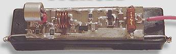
AN IMPROVED DESIGN
This design uses a "slug tuned coil" to
set the frequency. This means the slug can be screwed in and out of the
coil. This type of circuit does not offer any improvement in stability
over the previous circuit. (In later circuits we will show how to
improve stability. The main way to improve stability is to add a
"buffer" stage. This separates the oscillator stage from the output.)
The antenna is connected to the collector of the transistor and
this "loads" the circuit and will cause drift if the bug is touched. The
range of this circuit is about 200 metres and current consumption is
about 7mA. The microphone has been separated from the oscillator and
this allows the gain of the microphone to be set via the 22k resistor.
Lowering the resistor will make the microphone more sensitive. This
circuit is the best you can get with one transistor.
THE COIL
I have particularly
avoided mentioning the actual value (inductance in microhenry) of the
coil because it is less than 1uH and is about 0.65uH. That is 65nH
(65 to 80 nano Henry). A coil of this inductance will be very hard to
measure on an inductance meter, but if you want to measure it, here is
the secret:
Place a 1uH inductor on the inductance meter and read the value. Now add
the 65nH inductor and the reading will increase to 1.65uH.
But a few turns of wire and a few circles of trackwork on a Printed
Circuit Board will produce the same 65nH reading but the coil will
produce a much better result in the transmitter.
This is all to do with a term called EFFICIENCY or "Q" of the coil and
in the controlled conditions of these oscillators, the best coil will
"deliver back" nearly 100% of the energy it is supplied. This result in
a waveform in the antenna of nearly twice the voltage of the supply.
The other secret in producing a good output is to have the capacitor and
coil "match" each other.
In other words, the energy delivered back from the coil is the same as
the energy delivered back from the capacitor.
That's why the capacitor should be 39p and the coil 5 or 6 turns.
You can use 47p and a coil of 5 or 6 turns.
Stretching the coil reduces the inductance and this is how the two are
matched together and produce a frequency somewhere in the region of
85MHz to 110MHz.
For 39p and 65nH the resonant frequency will be 100MHz from a
calculator. But this may be different in a circuit due to the effect of the transistor.
For 47p and 70nH the resonant frequency will be 88MHz.
MORE STABILITY
If you want more stability, the antenna can be tapped off the top of the
tank circuit. This actually does two things. It keeps the antenna away
from the highly active collector and turns the coil into an
auto-transformer where the energy from the 8 turns is passed to a single
turn. This effectively increases the current into the antenna. And that
is exactly what we want.
The range is not as far but the stability is better. The frequency will
not drift as much when the bug is held. As the tap is taken towards the
collector, the output increase but the stability deceases.
LOW-VALUE
EMITTER RESISTOR
The next circuit has been picked out for its low emitter resistor on the
oscillator.
This resistor does not have to be a very low value as the transistor is
working at its maximum potential, due to the high frequency and a low emitter resistor will
simply consume more current without improving the output.
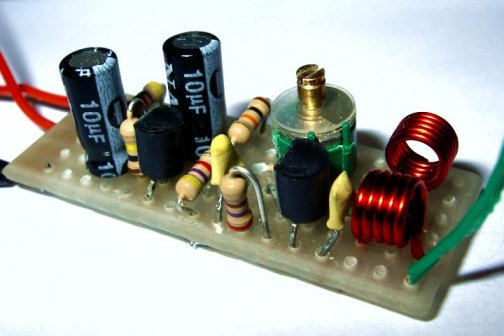
The emitter resistor is too low
Two photos of the bug
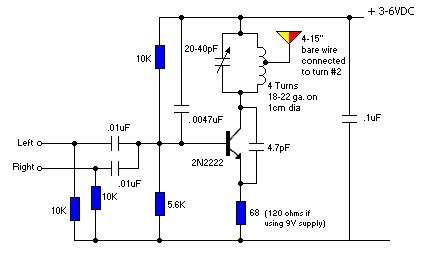
STEREO TO MONO
To combine two
channels to a mono output, the following circuit can be used:
INDUCTOR
Some time soon
you will come across a circuit with an inductor in
the emitter. This can be in a transmitting circuit or receiving
circuit.
Let's look at what is does and how it works.
The following circuit is a common-base COLPITTS circuit and oscillates
at 303MHz.
The components that set this frequency are: the length of the track on
the PC board (shown in thick black) and the value of the capacitor
across this track.
The component that makes this a "common-base" circuit is the capacitor
on the base.
The 1n has a capacitive reactance of less than
ONE OHM at 303MHz!
This means the base will not move up and down during the time when the
stage is oscillating.
The circuit turns ON via the 22k resistor and this is
because it puts a voltage on the base that is 0.7v higher than the
emitter. The current delivered by the 22k can now turn the
transistor ON a certain amount - BUT it is not allowed to turn the
transistor ON fully. If it did, the other components in the circuit (that
turn the transistor ON - by an increased amount) would not be needed and
there would be no components in the circuit to turn it OFF.
So, we have the first part of the cycle where the 22k starts to turn the
transistor ON.
Before we go any further, we have to mention the second way a transistor
can be turned ON.
If we hold the base of a transistor rigid and "pull" the emitter lead
towards the 0v rail, the "gap" between the base and emitter will
increase and although this increase may be only a few millivolts, it
will cause the transistor to turn on MORE.
Now, there is one more thing we have to cover.
When the voltage on the collector falls, due to the transistor turning
ON, the energy in the 3p3 will be passed to the emitter to reduce the
voltage on this lead.
But there is more to this. When the transistor turns ON, the relatively
high voltage across the 3p3 will be converted to a much lower voltage to
push the emitter lead a few millivolts lower but the current it will
deliver will be considerable.
The emitter lead is considered to be a very low impedance lead and it
requires a considerable current to move it lower.
Let me explain the capacitor phenomenon again:
You already know about this phenomenon, but have forgotten.
If you take a large electrolytic and charge it on a 12v battery with a
resistor in series, the capacitor will take a long time to charge and
the current-flow will be quite small.
Now take the electrolytic and short the 2 leads on the shaft of a
screwdriver. You will see a bright flash and the screwdriver will be
"burnt."
That's because the electrolytic is capable of receiving a low current
over a long period of time and releasing a high current for a short
period of time.
The 3p3 is doing the same thing.
The low impedance of the "emitter circuit" is due to two things. It is
due to the junction inside the transistor and the 100 ohm resistor.
If we were able to remove the 100 ohm resistor, the impedance of the
"emitter circuit" would increase - but obviously the circuit
would not work.
If the impedance of this part of the circuit is increased, the 3p3 will
be able to turn the transistor ON more and thus the overall amplitude of
the circuit will increase.
That's exactly what the inductor does. It effectively moves the 100 ohm
resistor away from the emitter lead so the 3p3 sees the "emitter
circuit" as a higher impedance.
How does it do this?
Firstly you have to understand how an inductor works when placed in this
type of circuit.
The circuit above is called an LC HIGH PASS FILTER.
It only allows high frequency signals to pass through the filter.
The signal enters from the left and the left lead of the first capacitor
rises and falls and passes this action to the right plate.
The incoming signal is not reduced by the capacitor if the signal has a
high frequency.
This means the incoming signal appears on the top of the inductor
with very little attenuation.
When the signal rises, a small amount of current enters the inductor and
produces magnetic flux. This flux is called EXPANDING FLUX and it cuts
all the other turns of the "coil" and produces a voltage in these turns
that is of opposite polarity to the incoming voltage. Say the incoming
voltage is 10v. The inductor will produce a voltage of 9.999v and
this means only 1 millivolt is available to deliver a current into the
inductor.
The end result is this: only a very small current will flow into
the inductor.
Exactly the same thing will happen when the voltage is falling.
The inductor will have very little "grip" on the voltage and it will
allow the voltage to "pass over" the inductor without reducing its
amplitude.
The "out" capacitor will pass the amplitude without reducing it and so
the incoming waveform will pass though this circuit without being
effected.
If the waveform has a low frequency, the first capacitor will attenuate
it and the inductor will reduce it and the "out capacitor" will reduce it.
The output will be almost zero.
Now, how does the inductor in the 303MHz circuit work?
It allows the signal from 3p3 to enter the emitter lead and have very
effect on attenuating the amplitude.
If the inductor were just a short length of wire, it would not have the
same effect and a lot of energy from the 3p3 would be passed to the 100
ohm resistor.
I know the two circuits are not identical, but the basics are still the
same.
The addition of an inductor DOUBLED the range of another transmitter
circuit we were testing in the laboratory and
when you realise the extra power needed to do this (about 8 times), its
effectiveness is very impressive.
Look at it this way: Pretend the signal from the 3p3 is a waveform
going down a large pipe that has sticky honey on the top and bottom of
the pipe. As the waveform hits the top and bottom, it get suck to the
honey an eventually its amplitude is reduced.
Now replace the honey with la bright shiny pipe. As the
wave reaches the top and bottom of the pipe it bounces off with very
little loss and the
amplitude is hardly affected. It will get to the end with very
little attenuation.
Unless you can see the operation of a circuit as things that "move" you
will not be able to diagnose or improve these circuits.
It's because most lecturers don't understand these circuits, that they
cannot impart a visualization that the students will remember.
One very clever lecturer said to the class: DO YOU KNOW?
DO YOU KNOW THAT YOU KNOW?
In other words, half-understanding is: NO UNDERSTANDING.
2 TRANSISTOR CIRCUITS
The next progressive step is to add a transistor to give the
electret microphone more sensitivity. The electret microphone contains a
Field Effect Transistor and you can consider it to be a stage of
amplification. That's why the electret microphone has a very good
output.
A further stage of amplification will give the bug extremely good
sensitivity and you will be able to pick up the sound of a pin dropping
on a wooden floor.
Many of the 1 transistor circuits over-drive the microphone and this
will create a noise like bacon-and-eggs frying. The microphone's used by
Talking Electronics require a load resistor of 47k for a 6v supply and
22k for a 3v supply. The voltage across the microphone is about 300mV to
600mV. It will produce an audio waveform of about 2-20mV.
Only a very simple self-biasing common-emitter stage is needed for the
audio amplifier. This
will give a gain of approx 70 for a 3v supply. The next circuit shows
this audio amplifier, added to the previous transmitter circuit. This
circuit is the best design using 2 transistors on a 3v supply. The
circuit takes about 7mA and produces a range of about 200 - 400metres.
2 Transistor FM Transmitter
Five points to note in the circuit above:
1. The tank circuit has a fixed 39p and is adjusted by a 2-10p trimmer.
The coil is stretched to get the desired position on the band and the
trimmer fine tunes the location.
2. The microphone coupling is a 22n ceramic. This value is sufficient
as its capacitive reactance at 3-4kHz is about 4k and
the input to the audio stage is fairly high, as noted by the 1M on the
base.
3. The 1u between the audio stage and oscillator is needed as the base
has a lower impedance as noted by the 47k base-bias resistor.
4. The 22n across the power rails is needed to keep the rails "tight."
Its impedance at 100MHz is much less than one ohm and it improves the
performance of the oscillator enormously.
5. The coil in the tank circuit is 5 turns of enameled wire with air
core. This is much better than a coil made on a PC board and is cheaper
than a bought inductor. The secret to long range is high activity in the
oscillator stage. The tank circuit (made up of the coil and capacitors
across it) will produce a voltage higher than the supply voltage due to
the effect known as "collapsing magnetic field" and this occurs
when the coil collapses and passes its reverse voltage to the capacitor.
The antenna is also connected to this point and it receives this high
waveform and passes the energy to the atmosphere as electromagnetic
radiation.
When the circuit is tightly constructed on a PC board, the frequency
will not drift very much if the antenna is touched. This is due to the
circuit design and layout as well as the use of large-value capacitors
in the oscillator. If low value capacitors are used, the effect of your
body has a greater effect on changing the frequency.
THE VOYAGER
The only way to get a higher output from two transistors is to
increase the supply voltage.
The following circuit is available from Talking Electronics as a
surface-mount kit, with some components through-hole. The
project is called THE VOYAGER.

All the elements of good design have been achieved in this project.
The circuit has a higher output than the 3v circuit above, but
most of the voltage is lost across the emitter resistor and not
converted to RF. The main advantage of this design is being able to
connect to a 9v battery. In a technical sense, about half the energy is
wasted as the stages actually require about 4v - 5v for maximum output.
The Voyager has been copied by many kit-makers but none has surpassed
its performance.
Here is a "knock-off" of our older design. It is mounted flat on a 9v battery:
Here are 2 more two-transistor circuits using a 9v
supply. We have also included the technical limitations of the
circuits:
DAVID'S DESIGN:
 |
|
Faults with this circuit: |
EMITTER CAPACITOR
The circuit above
has a 56p on the emitter. This capacitor has no effect on improving the
operation of the circuit and merely requires the capacitor connected
between the collector and emitter to be increased to counter the losses
delivered to the 56p.
The two 56p on the output do not improve the performance as they are
equivalent to 28p across L2 and this forms a tuned circuit. The aim of
the output stage is to be untuned so that any frequency can be selected
for the oscillator. If the output is "tuned" it will only have gain at
one particular frequency and will have to be re-tuned every time the
main frequency is altered.
A BIRD'S NEST DESIGN
Faults with this circuit:
1. Load resistor for microphone is very low - should be 47k
2.10u on output of microphone is not needed - 22n is
sufficient.
3. Current through audio state is very high. Load resistor
should be 47k
4. Base biasing of oscillator very wasteful.
5. Load resistor for oscillator (emitter resistor) is very low
6. Feedback capacitor for oscillator should be 10p.
7. No ceramic in tank circuit. Adding a ceramic makes it
easier to adjust
the trimmer capacitor.
8. No capacitor across the battery.
See the layout below: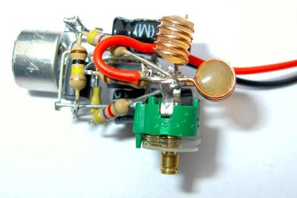
There is nothing wrong with a
bird's nest. It is very easy to experiment with
components and wiring that can be seen and changed without having to
work on a PC board. The only problem with the bird's nest above is
the lack of an earth plane. When you have an earth plane, the signal
can push against the large mass of an earth rail (or battery) so that it
can push the signal out the antenna.
The oscillator components must be kept near each other,
otherwise the circuit will not oscillate!