Library of Routines
for PIC12F629
Nearly all these instructions also work
with
PIC16F628. Just check on Port value(s) and
first available file.
see: Talking Electronics
website
A-E
E-P
P-Z

See the article
Start Here with PIC12F629 for helpful
programming notes and a map of the files.
The following is a list of sub-routines, ideas, and help for the PIC12F629. They
apply to any project using the PIC12F629.
They can be put into your program and modified in any way - to
suit the input/output lines.
The "Copy and Paste" version of these
sub-routines can be found HERE.
Your program should be created on a template in a text editor such as NotePad,
using blank12F629.asm as a starting layout.
It provides the correct layout and spacing.
An unusual problem you may get is a failure to compile your program due to hidden
formatting/characters.
MPASM
will not produce the needed .hex file if any problem exists in a
program but it will produce a .lst file containing the faults. If you
open .lst and see unusual
mistakes, they will be due to hidden formatting characters. Simply retype all
the wording around the mistake (in the .asm file) and the program will compile. Do
not use EditPad as it produces hidden characters.
To use the Library of Routines below, go to the NotePad set of "Copy and Paste"
Routines and "Copy and Paste" them into your program in
another NotePad, as needed.
Additional sub-routines can be found in the
PIC Programming
Course. This is on the subscription section of the website.
Make sure each sub-routine uses a file (a register) with a name (a hex number) that doesn't
clash with any other sub-routine you have created.
Make sure CALLs go to a sub-routine that has a RETURN (use retlw 00)
to bring the micro back to the correct pace in the program and create Labels
that let you know what the sub-routine is doing.
The following library is presented in alphabetical order. Using these sub-routines will get you started very quickly and will assist you
with 70% - 90% of a new project.
Read through the entire library so you know what is possible.
Simply think of a word or requirement, go to the
word and read about it. Many of the sub-routines are also available in the "Copy
and Paste" section.
Paste them into your program and modify them to suit. The micro will take each
instruction and carry it out. Make sure you have a RETLW 00 that brings the micro back to Main.
Get each sub-section working correctly before adding more instructions. Gradually
build up your program and save it as a NEW NAME so it can be recalled if a
major problem develops. Do not save it as the previous name as MPASM will
sometimes not assemble it (it will think it has
already been assembled and - do nothing!!) and you will wonder why the
improvements do not work!!
Add a
value to a File
The PIC12F629 does not have a single instruction to add a number to a file. Two
instructions are needed to carry out this operation.
Add
|
MOVLW 0CCh
ADDWF 2Eh,1 |
;Put CCh into W
;CC will be added to the contents of file
"2E." |
|
Add "bits" to a port - turn on
bits or "lines."
This is handy when more than one output line needs to be turned on.
|
MOVLW 10h
IORWF GPIO,1 |
;suppose GPIO has bits 0, 1 and 2 HIGH and we need
; to turn on bit 5
;Put 10h into W - this is bit 5
;10h will be added to the contents of file
"05." |
|
alternately, bit 5 can be SET
bsf GPIO,5
If more than one line needs to be made "HIGH" or "LOW," at the same time,
you need to use:
movlw xxh
iorwf GPIO,1
This is necessary as the PIC12F629 will fail to set two or more lines via
the following instructions:
bsf GPIO, 0
bsf GPIO, 2
The author has found the PIC12F629 will fail to set the second line.
Turn ON 2 or more outputs
The PIC12F629 does not like:
bsf GPIO, 0
bsf GPIO, 2
gpio,2 will not turn ON.
To turn ON, say gpio,0 gpio,1 and gpio,2 at the same time, use the
following:
You do not need to know the state of the other outputs, and they will not
be altered.
movlw b'00000111'
iorwf gpio,1
the result: gpio,0 gpio,1 and gpio,2 will be "set"
(go to "1" - high) and gpio,3 gpio,4 gpio,5 will not be affected.
The same can be done to turn OFF 3 outputs:
movlw b'00000000'
iorwf gpio,1
result: gpio,0 gpio,1 and gpio,2 will be "clear" (go
to "0" - low) and gpio,3 gpio,4 gpio,5 will not be affected.
This is NOT the same as: clrf gpio
Address a
File
This means "to act on" or "work with" a file. It can be to
"move a value into a file," "increment a file,"
"decrement a file" or other
similar operation. Only files can be addressed (the instructions in the
program cannot be address or altered). The files we are talking
about are the "empty" files from 20h to 5F. None of the program
or the values in the tables can be altered. The values in a table can be
accessed and copied by a set of instructions covered in CALL Table.
Typical addressing instructions are:
|
MOVWF 2A,0
DECFSZ 2A,1
INCF 2A,1
INCF 2A,0 |
;Copy file 2A into W
;Decrement file 2A
;Increment file 2A
;will put the increment of file 2A into W but file 2A will not
alter!! |
|
Addressing a Set of Files
A number of files can be used to store temporary data, such as the digits or
letters of a score-board.
This is sometimes called a "scratchpad" or "scratchpad
area." The files should be sequential to make programming
easy.
Suppose we have 8 files and need to address them with a simple sub-routine to
output the data to a display. The sub-routine is called INDIRECT ADDRESSING.
See Indirect Addressing.
ALL THE FLAGS AND
BITS
Here are some of the common flags and
bits.
For the other flags, see
PIC12F629
Data Sheet
(.pdf 4,926KB)
bank
select:
|
bsf 03,5
bcf 03,5 |
selects bank 1 - this is where the OPTION register is accessed.
selects bank 0 - this is the normal programming area |
| carry |
03,0 |
Test
the carry bit:
btfss 03,0 ;skip if a carry-out of the most
significant bit has
occurred. |
prescaler
assigned to
WDT |
bsf
Option_reg,3
or:
bsf 81h,3 |
see:
Watchdog timer
Option register is in bank 1 |
prescaler
assigned to
Timer0 |
bcf
Option_reg,3
or:
bcf 81h,3 |
Timer0 is in bank 0 |
| GPIO |
file
05h |
see
input/output port. "Setting the port bits HIGH or LOW" |
|
TRISIO |
file
85h |
see
"Setting the ports bits input or output" |
|
Status |
file
03 |
Contains the carry, bank select and zero flags. |
zero flag
zero bit |
03,2 |
zero flag is bit 2 of file 03 (the STATUS file)
1 = The result of an arithmetic or logic operation is zero
0 =
The result of an arithmetic or logic operation is not zero
You can look at bit 2:
btfss 03,2 ; skip if the zero bit is SET |
|
AND - see also Mask
The AND operation will mask any or all the bits in a file. In this way you can
"remove" any bit or the upper or lower nibble etc.
The quickest way to perform the operation is as follows:
To mask (remove) the lower nibble, it is ANDed with F0h (written
as 0F0h)
To mask (remove) the upper nibble, it is ANDed with 0Fh (can be
written 00Fh)
Place the value (say countA) to be operated on, into w:
movf countA,w
andlw 0F0h
;only the upper 4 bits will be in w.
ARITHMETIC
OPERATORS AND PRECEDENCE
- see also Pseudo Instructions
| OPERATOR |
Example |
| $ |
Current/Return Program Counter |
goto $ + 3 |
| ( |
Left parenthesis |
1 + ( d * 4) |
| ) |
Right
parenthesis |
(length + 1) * 256 |
| ! |
NOT (logical complement) |
if ! (a == b) |
|
– |
Negation (2's complement) |
– 1 * length |
|
~ |
Complement |
flags = ~
flags |
| * |
Multiply |
a = b * c |
| / |
Divide |
a = b / c |
| % |
Modulus |
entry_len = tot_len % 16 |
| + |
Add |
tot_len = entry_len * 8 + 1
|
|
– |
Subtract |
entry_len = (tot
– 1) / 8 |
| << |
Left Shift |
flags = flags << 1 |
| >> |
Right Shift |
flags = flags >> 1 |
| >= |
Greater or equal |
if entry_idx >= num_entries |
| > |
Greater than |
if entry_idx > num_entries |
| < |
Less than |
if entry_idx < num_entries |
| <= |
Less or equal |
if entry_idx <= num_entries |
| == |
Equal to |
if entry_idx == num_entries |
| ! = |
Not equal to |
if entry_idx ! = num_entries |
| & |
Bitwise AND |
flags = flags & ERROR_BIT |
| ^ |
Bitwise EXclusive OR |
flags = flags ^ ERROR_BIT |
| | |
Bitwise Inclusive OR |
flags = flags
|
ERROR_BIT |
| && |
Logical AND |
if (len == 512) && (b == c) |
|
|
| |
Logical OR |
if (len == 512)
|
| (b == c) |
| = |
Set equal to |
entry index = 0 |
| += |
Add to, set equal |
entry index += 1 |
|
–
= |
Subtract, set equal |
entry index
–
= 1 |
| *= |
Multiply,
set equal |
entry index
*= entry_length |
| /= |
Divide,
set equal |
entry total /= entry_length |
| %= |
Modulus,
set equal |
entry index %= 8 |
| <<= |
Left shift,
set equal |
flags <<= 3 |
| >>= |
Right shift,
set equal |
flags >>= 3 |
| &= |
AND,
set equal |
flags &= ERROR_FLAG |
|
| = |
Inclusive OR,
set equal |
flags
| =
ERROR_FLAG |
| ^ = |
EXclusive OR,
set equal |
flags ^= ERROR_FLAG |
| ++ |
Increment |
i ++ |
| –
– |
Decrement |
i
–
– |
Average
The following routine will produce the average of 4 values. Result in: Average
and Average+1.
cblock h'20' 	;start of general purpose registers
Buffer:8 		;Buffer has 8 files
Average:2 		;Average,      Average+1 will contain overflow
endc

	movlw Buffer 	;get Buffer address
	movwf FSR 	;point FSR at Buffer
Av 	call GetADC 	;read the ADC
	bsf STATUS,RP0 	;bank 1
	movwf ADRESL 	;get the low byte
	bcf STATUS,RP0 	;back to bank 0
	movwf INDF 	;store in buffer
	incf FSR,F 	;and point to next location
	movwf ADRESH 	;get high byte
	movwf INDF 	;and store it
	incf FSR,F 	;point to next location
	movfw FSR 	;see if FSR has reached
	xorlw Buffer+8 	;the end of the buffer
	movlw Buffer 	;prepare to reset FSR
	btfsc STATUS,Z 	;if it's at the end
	movwf FSR 	;reset it

	movfw Buffer 	;move first value to average
	movwf Average
	movfw Buffer+1 	;and high byte
	movwf Average+1

	movfw Buffer+2 	;add second value
	addwf Average,f 	;first low byte
	btfsc STATUS,C 	;if there was an overflow
	incf Average+1,f 	;increment high byte
	movfw Buffer+3 	;and add in high byte
	addwf Average+1,f

	movfw Buffer+4 	;add third value
	addwf Average,f
	btfsc STATUS,C
	incf Average+1,f
	movfw Buffer+5
	addwf Average+1,f

	movfw Buffer+6 	;add fourth value
	addwf Average,f
	btfsc STATUS,C
	incf Average+1,f
	movfw Buffer+7
	addwf Average+1,f

	bcf STATUS,C 	;divide by 2
	rrf Average+1,f 	;by shifting high byte
	rrf Average,f 	;and then low byte
	bcf STATUS,C 	;divide by 4
	rrf Average+1,f
	rrf Average,f
BANK SELECT
When writing a program, all your instructions are
written in an area called bank0. However some of the registers are in other
banks and you need to go to these banks to load data into the selected file
(register) or read from the file.
The simplest way to go from bank0 to bank1 is to set rp0 in the status file:
bsf status,
rp0
To go from bank1 to bank0 the rp0 bit is cleared:
bcf status,
rp0
However you can use a directive that is recognised by the assembler called:
banksel
You can use the name of any register in the bank you wish to select with the
banksel directive, such as:
banksel trisA
banksel trisio
to go to bank0:
banksel 0x00 or 00h
Here is the list of files for a PIC12F629 in
bank0 and bank1:
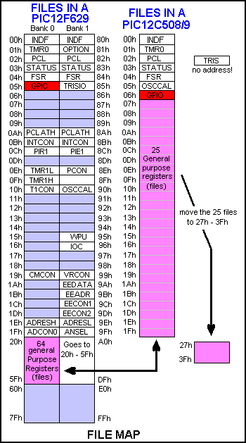
After accessing a file in Bank1, you must go to
bank0, by adding the instruction:
bcf status,
rp0
or
banksel 0x00 to continue with
your program.
Beep see
Tone
A Beep is a tone of short duration.
Binary to HEX:
see Decimal to Binary to HEX
Binary Hex and Decimal numbers
Any mixture of binary, Hex and decimal numbers can be
shown in a program.
Binary numbers are presented as: 0b00000000' or b'00000000' or B'00000000'
or 00000000b or b'0100'
indicates the lowest 4.
Hex numbers are shown as: 0x2 or 0x0F (=
fifteen) or 0x3C or h' or $
or <digits>h (must begin with 0 ....9)
Decimal numbers are shown as: d'250'
or decimal numbers without a prefix.
Block Transfer
A block of data can be transferred to another location
via the following sub-routine:
12 bytes at address 30h - 3Bh to transfer to 50h - 5Bh
Transfer
	movlw	0Ch
	movwf	temp1	;no of loops
	movlw	30h	;start of 1st block
	movwf	04h	;load FSR
	movf	00h,0	;move value looked at by FSR into W
	bcf	04h,5
	bsf	04h,6	;turns FSR 30h to 50h
	movwf	00h
	bsf	04h,5
	bvf	04h,6	;turns FSR 50h to 30h
	incf	04h,1
	decfsz	temp1,1
	goto	$-8
	retlw	00
Burning
BURNING means programming and is a simple way to distinguish from
when you are creating a program as this is also called “Programming.”
You can get a printed circuit board from Talking Electronics to hold an
8-pin or 18 pin PIC chip and it connects to a PIC pro 2 or 3 to make it easy to program
chips. It has a set of LEDs on the board that illuminate when programming
and also flash when the chip is burnt. (for some programs). The module costs
less than $10.00 posted It comes as a kit and requires soldering surface-mount
LEDs.
It is absolutely essential for programming. And it is surprising that no-one
has created anything like i
Button see Switch
bz
-
branch on zero flag being set to
"1" See more instructions in "MACRO."
NewSw
timeout | movf
Sw,0
bz timeout
xxxxxxx
yyyyyyyyy
|
;Move file "Sw" to W
;If Sw file is zero, the result of moving it to w (or to itself)
will
;set the zero flag to "1" and the micro will goto "timeout." | |
CALL
see also Stack
CALL means to branch to, and return from a subroutine. It does NOT
mean GOTO. GOTO means to branch unconditionally and maybe not return
to the present routine. CALL means to branch to another sub-routine
and RETURN to the next address. Every CALL must have its own RETURN or RETLW
00 to 0FFh statement.
Use only RETLW 00. Do not use RETURN.
When a CALL instruction is executed, the next
address-value is placed on the stack and the micro goes to the location
identified in the instruction.
Do not "GOTO" a sub-routine that has a RETURN at the end of it. The micro
will not know where to return as the GOTO instruction does not put a return
address into memory (the stack).
The CALL instruction works to the full 1024 locations in a PIC12F629 chip.
And the GOTO instruction works to the full 1024 instructions.
You can CALL a sub-routine by indentifying the name of the sub-routine and
the first instruction will be executed. Or you can execute the third
instruction in the sub-routine by: call time+2
USING THE CALL INSTRUCTION
The micro will come to CALL Delay in the sub-routine below. It will then advance down the program to
Delay and carry out instructions until it reaches RETLW 00. The micro will
then move up the program to the xxxxxxxxx line.
Delay
DelA
|
CALL
Delay
xxxxxxxxx
- - - - - - - -
- - - - - - - -
- - - - - - - -
MOVLW
80h
MOVWF 2A
DECFSZ 2A,1
GOTO DelA
RETLW 00 |
;Put
80h into W
;Copy 80h into file 21A
;Decrement file 21A
;Loop until file 2A is zero
|
|
CALL Table
see also Table and
Output a Table Value
The instructions CALL Table uses the value in W and adds it to the
Program Counter (PC - location 02 (file 02) - the ,1 indicates the
value in W will be placed in the Program Counter (file) to create a JUMP VALUE to jump down a Table and pick up a value. The
instruction beside each value in a table places the value in W and makes
the micro return to the instruction after CALL Table. The next instruction should
be to move the value from W to a file.
| Call
|
MOVF 2A,0
CALL Table
MOVWF 2C
|
;File 2A contains 05. Move it to W
;W will return with 6D
;Move 6D to file 2C | |
Table
|
ADDWF
02h,1
RETLW 3Fh
RETLW 06h
RETLW 5Bh
RETLW 4Fh
RETLW 66h
RETLW 6Dh
RETLW 7Dh
RETLW 07h
RETLW 7Fh
RETLW 6Fh
|
;Add W to the Program Counter to create a jump.
|
|
Carry
- see also ROTATE for one of the operations involving CARRY.
The carry bit is located in the STATUS register (file 03) and is bit
0.
The carry bit is SET when the result of an operation is larger than 0ffh.
The carry bit is SET when the result of an operation is less than zero.
It is cleared by the instruction:
BCF 03,0 - clear bit0 in file 03
Carry is SET by the instruction:
BSF 03,0
To test the carry:
BTFSS 03,0
GOTO AAA ;The micro will go HERE if the carry is NOT
set.
GOTO BBB
;The micro will go HERE if the carry is SET.
The carry is also used when a file is rotated left or right.
When a file is rotated left, the MSB (most significant bit (bit 7) is passed
into the carry and the carry-bit is passed into the file as bit 0. If you don't
want the "carry bit" to affect the outcome of the operation it must be cleared
before-hand, thus:
bcf 03,0
CBLOCK -
(define a Block of Constants)
This is a directive used for defining files that will be
reserved for an application. The format of CBLOCK is: cblock 0x20 ;define the start of the files. The first "file" or "register" for a 12F629 is 20h
Lowbyte ;this will be file 20h
Medbyte ;this will be file 21h
Hibyte ;this will be file 22h etc etc etc
endc
This method of declaring variables is quite good, but macros cannot take advantage of it.
The alternative to cblock is: Lowbyte equ 20h
Medbyte equ 21h
Hibyte equ 22h
cblock can use other files, starting at say 4Ch: The 3 files d1, d2 and d3 are files for a
delay routine and are files 4Ch, 4Dh and 4Eh.
cblock 0x4C
d1
d2
d3
endc
Another method of defining files is:
| |
org 20h
save ds 1
flag ds 2
count ds 1
csave ds 1
temp ds 2
ontime ds 1
oftime ds 1
timer ds 3
freq ds
2
mode ds 1
rate ds 1
hi ds 1
low ds 1
delay ds 3
|
The compiler will allow one file (20h) for "save" and two files for "flag."    timer will be given 3 files.

When writing the program, you write the instruction such as     incf    flag,1  for the first flag file and
btfss   flag+1   for the second flag file.

Another way to define fines in cblock:

cblock 0x20	   ;define the start of the files. The first "file" or "register" for a 12F629 is 20h
delay		   ;this will be file 20h
delay2		   ;this will be file 21h
timing,timing3,timing6	   ;file 22h,23h,24h
detect:4                                             ;file 25h,26h,27h,28h    Note ":4"indicates 4 files are needed.

endc
Change Direction
The direction of an input/output line (or a whole port) can be changed at any
time during the running of a program. The file we are loading or
setting or clearing is file 85. It is in Bank 1. This file is called TRISIO.
|
BSF 03,5
BSF TRISIO,1
BCF 03,5 |
;Go to Bank 1
;Make GP1 input
;Go to Bank 0 - the program memory area. | |
|
BSF 03,5
BCF TRISIO,1
BCF 03,5 |
;Go to Bank 1
;Make GP1 output
;Go to Bank 0 - the program memory area. | | See also: SetUp for setting up the Input/Output lines. See Input for the instruction(s) to make a line
Input. See Output to make a line Output. Lines are changed
by setting or clearing bits of the TRISIO register. This is called BIT
MANIPULATION. This prevents touching (and upsetting) other lines. See Toggle to change the STATE of a line (from HIGH to LOW
or LOW to HIGH).
Clear
a list of files (registers)
ClrLoop |
movlw StartFile
movwf FSR
clrf
INDF
incf FSR,f
movlw EndFile
subwf FSR,w
btfss status,z
goto ClrLoop |
;FSR is loaded with the
value of the first file to be cleared
;
;INDF is file 00 and this command actually clears the
file
looked-at by FSR
;advance to next file
;Load FSR with value of End File
;perform a subtraction
;zero bit will be set when result is zero - end file
reached
| |
;clear EEPROM
clear movlw .22 ;the number to be cleared
movwf loops
bsf
status,rp0 ;select bank1
clrf
eeadr
decf eeadr
;to start at first address
bsf
status,rp0 ;select bank1
incf
eeadr,1
clrf
eedata ;put a blank at each
address
bcf
status,rp0 ;select bank0
call
write
decfsz loops,1
goto
$-6
retlw
00
Clear and Set
These are two terms that are used in two of the institutions.
btfss gpio,0 This instruction means: “test the pin and skip if the
reading is high.
btfsc. gpio,0 This instruction means: “test the pin and skip if the reading
is zero.”
Here is a sample instruction:
btfss gpio,0 gpio refers to one of the files that is connected directly to
pins 2,3,4,5,6,7 and these pins are the input/output pins for the
microcontroller.
Here’s how the instruction works
btfss gpio,0
goto $+3
goto $+5
The instruction looks at pin 7 of an 8-pin PIC microcontroller.
This pin has been turned into an input pin via instructions at the beginning
of the program.
It has to be an input to detect signals on the pin.
If the voltage on the pin is above 2.5v it is considered to be HIGH.
This
means the pin is seeing a SET = “s”
The instruction says: if pin 7 sees a HIGH, the micro will go to the third instruction,
which is: goto $+5, and land on an instruction that is five instructions
down the program and execute the instruction at that location.
If the voltage on pin7 is below 2v, the micro sees a LOW = “c” and the
program goes to the second instruction: goto $+3 which is 3 instructions down the program
and executes the instruction at that location.
The instructions above provide two “branches” or “goto’s”
The following instructions provide just one branch.
btfss gpio,0
goto $+8
movlw .23
The micro will look at pin 7 and if it is LOW, it will go to the
instruction 8 instructions below. That is because the instructions asks for
a HIGH to go to movlw .23
How to use the “clear” and “set” instruction.
The instruction btfss gpio,0 will detect if a pin is seeing a signal (or
voltage).
This action is called “Polling.”
The signal needs to be present on the pin and the program and the micro
comes to it in the
normal way and when it comes to the instruction, the program will perform
the operation.
The signal just “sits there” waiting for the program to come to the
instruction.
If the signal only appears for a very short time, you need to look at the
instruction on a regular basis. This is called “looping” or “polling.”
You can get the program to come to the pin when it changes state by setting
the state of the pin in the program during programming. But we have not
covered this as it is quite complex.
The letter “c” means “clear” and refers to the value “0” or LOW
The letter “s” means “set” and refers to the value “1” or HIGH
At the beginning of a program, the pins are set-up as input or output via
the following four instructions:
bsf
status,rp0 ;Bank 1
movlw
b'00000110' ;Set TRIS
movwf
TRISIO
bcf
status, rp0 ;bank 0
When a pin is created as an INPUT, the value “1” is placed in the location
corresponding to the pin in the instruction: movlw where the lowest number
represents gpio,0 and when the value is “0” the pin is an Output.
When the number is “1” the pin is an input.
In the instructions above, pin 7 is an output, pin 6 is an input, pin 5 is
an input, pins 4,3,2 are outputs.
The other two places in the file are not used.
When the number is “1” the pin is an input.
You must connecte something to the pin that will make it received a zero
signal or a HIGH signal.
The low signal needs to be from 0v to about 2v and the high signal needs to
be above 2.5v
The instruction btfss gpio,0 means to test the lowest of the six input pins,
(which is pin7) and skip the next instruction if it sees a HIGH.
btfsc gpio,0 and skip the next instruction if it sees a LOW
Don’t let an input pin ”float”. Make sure it is being “held” or “taken” HIGH
or LOW.
SUMMARY:
c = clear = LOW
s = set = HIGH
Turn ON 2 or
more outputs
The PIC12F629 does not like:
bsf GPIO, 0
bsf GPIO, 2
gpio,2 will not turn ON.
To turn ON, say gpio,0 gpio,1 and gpio,2 at the same time, use the
following:
You do not need to know the state of the other outputs, and they will not
be altered.
movlw b'00000111'
iorwf gpio,1
the result: gpio,0 gpio,1 and gpio,2 will be "set"
(go to "1" - high) and gpio,3 gpio,4 gpio,5 will not be affected.
The same can be done to turn OFF 3 outputs:
movlw b'00000000'
iorwf gpio,1
result: gpio,0 gpio,1 and gpio,2 will be "clear" (go
to "0" - low) and gpio,3 gpio,4 gpio,5 will not be affected.
This is NOT the same as: clrf gpio
Compare
To compare two values, you can use XOR.
To compare two numbers, they are XORed together and if they are the same, the Z flag will be set. Take two numbers:
number = 7A = 0111 1010
W = 7A
= 0111 1010
Starting at the right hand end, ask yourself the question, "Is one OR the other a 1?" The answer is no. The next column. "Is one number OR the other a 1?" No BOTH the numbers are 1! so that's why the answer is NO. In this way every column has the answer NO, when both numbers match.
When all the answers are Zero, the flag rises! to say the result is ZERO. In other words it is SET.
To find the zero flag look in the STATUS register, bit 2, i.e. File 03,2.
e.g: To compare two files:
MOVF 2A,0 ;Move one file into W
XORWF 2B,0 ;XOR W and 2B
BTFSS 03,2 ;Test Z flag
If Z flag is SET (ie 1) the two files are the SAME!
The same thing can be done by using the subtract operation:
MOVF 2A,0 ;Move one file into W
SUBWF 2B,0 ;Subtract W from 1B
BTFSS 03,2 ;Test Z flag
If Z flag is SET (ie 1) the two files are the SAME!
Same:
Z flag is SET (ie 1) when
the two files are the SAME!
Comparison
The contents of a file can be compared with the contents of the working register (W) to determine their relative magnitudes. This is done by subtracting the contents of W from the selected file. By testing the Carry and Zero flags, 4 results can be obtained:
E.g:
MOVLW 22h ;Put 22h in W
MOVWF 3C ;Move 22h to file 3C
MOVLW 15h ;Put 15h in W
SUBWF 3C,1 ;Subtract 15h from 22h
BTFSS 03,2 ;Test Zero flag
OR
BTFSS 03,0 ;Test Carry flag
Zero flag is SET if W = File value = Match
Zero flag is CLEAR if no Match
Carry flag is SET if a borrow did not occur (W is less than or equal to file value)
Carry flag is CLEAR if a borrow occurred (W is greater than file value)
(Put a value into W and perform SUBWF).
Test Carry:
More than:
Carry flag is CLEAR if W is greater than file
value.
Less than:
Carry flag is SET if W is less than or equal to file value.
Suppose a file (file 3E) is incremented to 8 such as in the
Logic Probe with Pulser.
We need to know if the file is 1, 2 or 3. The first thing to do is eliminate the
possibility of zero.
TestA
MOVLW 00h
;Eliminate file 3E if it is zero,
XORWF
3E,0
;XOR file 3E with W
BTFSC 03,2
;Test the zero flag to see if file 3E is zero
GOTO TestA1
;File 3E is zero
The SUBWF
operation below subtracts the W register (via a process called the 2's
complement method) from file 3E and the carry flag in the Option register (file 03)
will be SET if 3E is equal to W or more than W (i.e: 4 or more).
MOVLW 04
;Put 04 into W for subtract operation
SUBWF
3E,0
;Carry will be set if 3E is = or more than 4
BTFSS 03,0
;Test the carry flag
GOTO Hi
;Go to another sub-routine such as "Hi"
Here is the outcome for all the possibilities for file3E:
If 3E = 0 C = 0 (we have eliminated
the possibility of zero via the first 4 lines above)
If 3E = 1 C = 0 (carry is zero -
this is not the CARRY BIT it is the SET (1) or clear (0) indicator)
If 3E = 2 C = 0
If 3E = 3 C = 0 (carry is clear)
If 3E = 4 C = 1 (carry is set)
If 3E = 5 C = 1
If 3E = 6 C = 1
If 3E = 7 C = 1
If 3E = 8 C = 1
The carry bit in the Option file is bit 0. Therefore we test bit 0 of
file 03:
BTFSS 03,0
The result in 3E can only be 1, 2, or 3.
Config
- configuration
The configuration word is located at address
2007h and is only accessed during programming.
'__CONFIG' directive is used to embed configuration data within .asm file.
Note
the double underbar at the front of "config."
Some of the configuration settings:
_CP_OFF & _WDT_OFF & _BODEN_OFF & _PWRTE_ON
& _LVP_OFF
Each setting has a single underbar and a "&" sign, with a single space
between "&" sign.
All configuration settings (sometimes called "fuses") are "set" or "active"
when =1.
BUT three are "active" when set =0. This is called "active LOW"
They are: CP - Code Protect = active when = 0
CPD - Code Protect Data = active when = 0
PWRTE - Power-up Timer = active when = 0.
Use the following to set the "fuses:" (easy to read and
understand)
_CP_OFF & _WDT_OFF & _BODEN_OFF & _PWRTE_ON
& _LVP_OFF
By default, all config bits are initialized to "1"
Here is an example of how the configuration word is created:
; ----- Configuration Word
-----------
; Bandgap 11
Highest voltage (00 lowest voltage) for BOD and POR
; Unimplemented
000
Read as '0'
; Data code protection 1
CPD disabled (0=enabled)
; Code protection
1 CP
disabled (0 = program memory code protection enabled)
; Brown-out detect
1 BOD enabled
(0=BOD disabled)
; GP3/MCLRE
0 digital I/O, MCLR
internally tied to Vdd
; Power-up timer
1 PWRT disabled (0=PWRT
enabled)
; Watchdog timer
0 WDT disabled (0=WDT disabled)
; Oscillator
100 INTOSC I/O on GP4 & GP5
__config
b'11000111010100'
Oscillator:
000 = LP oscillator Low power crystal on GP4 and GP5
001 = XT oscillator Crystal/resonator on GP4 and GP5
010 = HS oscillator High Speed
crystal/resonator
on GP4 and GP5
011 = EC: I/O function on GP4 ClkIn on GP5
100 = INTOSC oscillator
I/O on GP4 & GP5
101 = INTOSC ClkOut on GP4 I/O on GP5
110 = RC oscillator I/O function on GP4 RC on GP5
111 = RC oscillator ClkOut on GP4 RC on GP5
Copy
bits from one file to another
To copy bit3:bit2 from "source" to bit7:bit6 "target"
|
movlw b'00111111'
andwf target,f
swapf source,w
andlw b'11000000'
iorwf target,f |
;
;clear target bit7:bit6
;the lower nibble of source will be swapped with
;high nibble and the result will be placed in w
;only the two top bits of source will remain
;the two top bits of source will be added to "target" | |
To copy bit3:bit2 from "source" to bit3:bit2
"target"
|
movf
source,w
andlw
b'00000011'
iorwf
target,f |
;move source into w
;only the
two lower bits of source will remain
;the two lower bits of source will be added to
"target" | |
Count
If you want to count the number of pulses from a push-button or
switch, the easiest way is to increment a file. A file will hold up to 255.
The result is stored as a hexadecimal number from 01 to FF.
If you want to count to three, pre-load a file with 3 and decrement it and
detect zero.
Data Table - see DT below
Debounce a Button (Switch)
See Switch and Poll
Debug
This is not a term used in creating a program in PIC language, however
we have two suggestions for finding a "bug" or problem
in a program.
1. Go back to your previously saved version and note the
differences in the programs. Try to visually detect the fault.
2. "Home-in" on the faulty section and see how
far the micro is getting through by inserting a Wait instruction.
(See Wait) A LED
on an output line will illuminate to indicate the micro has reached
the instruction.
Decimal,
Hex and
Binary
numbers
Any mixture of binary, Hex and decimal numbers can be
shown in a program.
Binary numbers are presented as: 0b00000000' or b'00000000' or B'00000000'
or 00000000b or b'0100'
indicates the lowest 4.
Hex numbers are shown as: 0x2 or 0x0F (=
fifteen) or 0x3C or h' or $
or <digits>h (must begin with 0 ....9)
Decimal numbers are shown as: d'250'
or decimal numbers without a prefix.
Decimal to Binary to HEX:
| |
|
|
|
|
|
|
|
|
|
|
| 0 | 0000 0000 | 0 | 16 | 0001
0000 | 10h | 32 |
0010 0000 | 20h |
| 1 | 0000 0001 | 1 | 17 | 0001
0001 | 11h | 33 |
0010 0001 | 21h |
| 2 | 0000 0010 | 2 | 18 | 0001
0010 | 12h | 34 |
0010 0010 | 22h |
| 3 | 0000 0011 | 3 | 19 |
0001 0011 | 13h | 35 |
0010 00110 | 23h |
| 4 | 0000 0100 | 4 | 20 |
0001 0100 | 14h | 36 |
0010 0100 | 24h |
| 5 | 0000 0100 | 5 | 21 |
0001 0101 | 15h | 37 |
0010 0101 | 25h |
| 6 | 0000 0110 | 6 | 22 |
0001 0110 | 16h | 38 |
0010 0110 | 26h |
| 7 | 0000 0111 | 7 | 23 |
0001 0111 | 17h | 39 |
0010 0111 | 27h |
| 8 | 0000 1000 | 8 | 24 |
0001 1000 | 18h | 40 |
0010 1000 | 28h |
| 9 | 0000 1001 | 9 | 25 |
0001 1001 | 19h | 41 |
0010 1001 | 29h |
| 10 | 0000 1010 | A | 26 |
0001 1010 | 1Ah | 42 |
0010 0010 | 2Ah |
| 11 | 0000 1011 | B | 27 |
0001 1011 | 1Bh | 43 |
0010 10110 | 2Bh |
| 12 | 0000 1100 | C | 28 |
0001 1100 | 1Ch | 44 |
0010 1100 | 2Ch |
| 13 | 0000 1101 | D | 29 |
0001 1101 | 1Dh | 45 |
0010 1101 | 2Dh |
| 14 | 0000 1110 | E | 30 | 0001 1110 | 1Eh | 46 | 0010 1110 | 2Eh |
| 15 | 0000 1111 | F | 31 | 0001 1111 | 1Fh | 47 |
0010 1111 | 2Fh |
| |
|
|
|
|
|
|
|
|
|
| |
|
|
|
|
|
|
|
|
|
|
| 48 |
0011 0000 | 30h | 64 | 0100
0000 | 40h | 80 | 0101
0000 | 50h |
| 49 | 0011 0001 | 31h | 65 | 0100
0001 | 41h | 81 | 0101
0001 | 51h |
| 50 | 0011 0010 | 32h | 66 | 0100
0010 | 42h | 82 | 0101
0010 | 52h |
| 51 | 0011 0011 | 33h | 67 | 0100
0011 | 43h | 83 | 0101
00110 | 53h |
| 52 | 0011 0100 | 34h | 68 | 0100
0100 | 44h | 84 | 0101
0100 | 54h |
| 53 | 0011 0100 | 35h | 69 | 0100
0101 | 45h | 85 | 0101
0101 | 55h |
| 54 | 0011 0110 | 36h | 70 | 0100
0110 | 46h | 86 | 0101
0110 | 56h |
| 55 | 0011 0111 | 37h | 71 | 0100
0111 | 47h | 87 | 0101
0111 | 57h |
| 56 | 0011 1000 | 38h | 72 | 0100
1000 | 48h | 88 | 0101
1000 | 58h |
| 57 | 0011 1001 | 39h | 73 | 0100
1001 | 49h | 89 | 0101
1001 | 59h |
| 58 | 0011 1010 | 3Ah | 74 | 0100
1010 | 4Ah | 90 | 0101
0010 | 5Ah |
| 59 | 0011 1011 | 3Bh | 75 | 0100
1011 | 4Bh | 91 | 0101
10110 | 5Bh |
| 60 | 0011 1100 | 3Ch | 76 | 0100
1100 | 4Ch | 92 | 0101
1100 | 5Ch |
| 61 | 0011 1101 | 3Dh | 77 | 0100
1101 | 4Dh | 93 | 0101
1101 | 5Dh |
| 62 | 0011 1110 | 3Eh | 78 | 0100 1110 | 4Eh | 94 | 0101
1110 | 5Eh |
| 63 | 0011 1111 | 3Fh | 79 | 0100 1111 | 4Fh | 95 | 0101
1111 | 5Fh |
| |
|
|
|
|
|
|
|
|
|
| |
|
|
|
|
|
|
|
|
|
|
| 96 | 0101
0000 | 60h | 112 | 0111
0000 | 70h | 128 |
1000 0000 | 80h |
| 97 | 0101
0001 | 61h | 113 | 0111
0001 | 71h | 129 | 1000
0001 | 81h |
| 98 | 0101
0010 | 62h | 114 | 0111
0010 | 72h | 130 | 1000
0010 | 82h |
| 99 | 0101
0011 | 63h | 115 | 0111
0011 | 73h | 131 | 1000
00110 | 83h |
| 100 | 0101
0100 | 64h | 116 | 0111
0100 | 74h | 132 | 1000
0100 | 84h |
| 101 | 0101
0100 | 65h | 117 | 0111
0101 | 75h | 133 | 10000
0101 | 85h |
| 102 | 0101
0110 | 66h | 118 | 0111
0110 | 76h | 134 | 1000
0110 | 86h |
| 103 | 0101
0111 | 67h | 119 | 0111
0111 | 77h | 135 | 1000
0111 | 87h |
| 104 | 0101
1000 | 68h | 120 | 0111
1000 | 78h | 136 | 1000
1000 | 88h |
| 105 | 0101
1001 | 69h | 121 | 0111
1001 | 79h | 137 | 1000
1001 | 89h |
| 106 | 0101
1010 | 6Ah | 122 | 0111
1010 | 7Ah | 138 | 1000
0010 | 8Ah |
| 107 | 0101
1011 | 6Bh | 123 | 0111
1011 | 7Bh | 139 | 1000
10110 | 8Bh |
| 108 | 0101
1100 | 6Ch | 124 | 0111
1100 | 7Ch | 140 | 1000
1100 | 8Ch |
| 109 | 0101
1101 | 6Dh | 125 | 0111
1101 | 7Dh | 141 | 1000
1101 | 8Dh |
| 110 | 0101
1110 | 6Eh | 126 | 0111 1110 | 7Eh | 142 | 1000 1110 | 2Eh |
| 111 | 0101
1111 | 6Fh | 127 | 0111 1111 | 1Fh | 143 | 1000 1111 | 8Fh |
| |
|
|
|
|
|
|
|
|
|
| |
|
|
|
|
|
|
|
|
|
|
| 144 | 1001
0000 | 90h | 160 | 1010
0000 | A0h | 176 |
1011 0000 | B0h |
| 145 | 1001 0001 | 91h | 161 | 1010
0001 | A1h | 177 | 1011
0001 | B1h |
| 146 | 1001 0010 | 92h | 162 | 1010
0010 | A2h | 178 | 1011
0010 | B2h |
| 147 | 1001 0011 | 93h | 163 | 10100011 | A3h | 179 | 1011
00110 | B3h |
| 148 | 1001 0100 | 94h | 164 | 1010
0100 | A4h | 180 | 1011
0100 | B4h |
| 149 | 1001 0100 | 95h | 165 | 1010
0101 | A5h | 181 | 11011
0101 | B5h |
| 150 | 1001 0110 | 96h | 166 | 1010
0110 | A6h | 182 | 1011
0110 | B6h |
| 151 | 1001 0111 | 97h | 167 | 1010
0111 | A7h | 183 | 1011
0111 | B7h |
| 152 | 1001 1000 | 98h | 168 | 1010
1000 | A8h | 184 | 1011
1000 | B8h |
| 153 | 1001 1001 | 99h | 169 | 1010
1001 | A9h | 185 | 1011
1001 | B9h |
| 154 | 1001 1010 | 9Ah | 170 | 1010
1010 | AAh | 186 | 1011
0010 | BAh |
| 155 | 1001 1011 | 9Bh | 171 | 1010
1011 | ABh | 187 | 1011
10110 | BBh |
| 156 | 1001 1100 | 9Ch | 172 | 1010
1100 | 7Ch | 188 | 1011
1100 | BCh |
| 157 | 1001 1101 | 9Dh | 173 | 1010
1101 | ADh | 189 | 1011
1101 | 8Dh |
| 158 | 1001 1110 | 9Eh | 174 | 1010 1110 | AEh | 190 | 1011 1110 | BEh |
| 159 | 1001 1111 | 9Fh | 175 | 1010 1111 | AFh | 191 | 1011 1111 | BFh |
| |
|
|
|
|
|
|
|
|
|
| |
|
|
|
|
|
|
|
|
|
|
| 192 | 1100
0000 | C0h | 208 | 1101
0000 | D0h | 224 |
1110 0000 | E0h |
| 193 | 1100 0001 | C1h | 209 | 1101
0001 | D1h | 225 | 1110
0001 | E1h |
| 194 | 1100 0010 | C2h | 210 | 1101
0010 | D2h | 226 | 1110
0010 | E2h |
| 195 | 1100 0011 | C3h | 211 | 1101
0011 | D3h | 227 | 1110
00110 | E3h |
| 196 | 1100 0100 | 64h | 212 | 1101
0100 | D4h | 228 | 1110
0100 | E4h |
| 197 | 1100 0100 | C5h | 213 | 1101
0101 | D5h | 229 | 11100
0101 | E5h |
| 198 | 1100 0110 | C6h | 214 | 1101
0110 | D6h | 230 | 1110
0110 | E6h |
| 199 | 1100 0111 | C7h | 215 | 1101
0111 | D7h | 231 | 1110
0111 | E7h |
| 200 | 1100 1000 | C8h | 216 | 1101
1000 | D8h | 232 | 1110
1000 | E8h |
| 201 | 1100 1001 | 69h | 217 | 1101
1001 | D9h | 233 | 1110
1001 | E9h |
| 202 | 1100 1010 | 6Ah | 218 | 1101
1010 | DAh | 234 | 1110
0010 | EAh |
| 203 | 1100 1011 | 6Bh | 219 | 1101
1011 | DBh | 235 | 1110
10110 | EBh |
| 204 | 1100 1100 | CCh | 220 | 1101
1100 | DCh | 236 | 1110
1100 | ECh |
| 205 | 1100 1101 | CDh | 221 | 1101
1101 | 7Dh | 237 | 11100
1101 | EDh |
| 206 | 1100 1110 | CEh | 222 | 1101 1110 | DEh | 238 | 1110 1110 | 2Eh |
| 207 | 1100 1111 | CFh | 223 | 1101 1111 | DFh | 239 | 1110 1111 | EFh |
| |
|
|
|
|
|
|
|
|
|
| |
|
|
| 240 | 1111
0000 | F0h |
| 241 | 1111 0001 | F1h |
| 242 | 1111 0010 | F2h |
| 243 |
1111 0011 | F3h |
| 244 | 1111 0100 | F4h |
| 245 | 1111 0100 | F5h |
| 246 | 1111 0110 | F6h |
| 247 | 1111 0111 | F7h |
| 238 | 1111 1000 | F8h |
| 249 | 1111 1001 | F9h |
| 250 | 1111 1010 | FAh |
| 251 | 1111 1011 | FBh |
| 242 | 1111 1100 | FCh |
| 243 | 1111 1101 | FDh |
| 254 | 1111 1110 | FEh |
| 255 | 1111 1111 | FFh |
| |
|
|
Decrement
To decrement a file, use the instruction:
DECF 3A,1. This puts the new value back into the file. Do not use DECF
3A,0 as the new value goes into W!
To decrement a file twice, use:
DECF 3A,1
DECF 3A,1
To halve the value of a file, the contents is shifted right:
RRF 3A,1- the file must not have a bit in bit0.
A file can be decremented until it is zero:
DECFSZ, 3A,1
To decrement W we can use the instruction: addlw -1
We can also decrement a file by adding a value to it.
For example we can decrement a file by an amount of .10 by adding
.246 to it. (0ffh = .256)
suppose file 3Ah has a value of .60
movlw .246 (ten less than a full file)
addwf 3Ah
file 3A will now contain .50
Delay
A delay sub-routine is needed for almost every program. One of the
main purposes is to slow down the execution of a program to allow
displays to be viewed and tones to be produced.
The shortest delay is NOP. This is a "do nothing" instruction
that takes 1 micro-second.
You will need one million "NOP's" to produce a 1
second delay.
Here are some instructions to produce a very short delay:
| |
nop
goto $+1
call $+2
goto
$+1
retlw 00 |
;1 microsecond
;
;2 microseconds
;
;3 instructions produce 2 + 2 + 2 +2 microseconds
;the micro will return to wherever the sub-routine was
;called from
|
|
It is impractical to use instructions with just a
microsecond delay as the program space will only allow about 1,000
instructions or 2,000 microseconds!
The answer is to create a loop. If a file is loaded with a value and
decremented, it will create a short delay. The two instructions: DECFSZ
3A,1 and GOTO DelA will take 3uS. 80h loops = 127
loops x 3 + 1 loop x 2uS + 2uS on entry + 1uS on exit
= 386uS
Del
DelA |
MOVLW
80h
MOVWF 3A
DECFSZ 3A,1
GOTO DelA
RETLW 00 |
;Put
80h into W
;Copy 80h into file 1A
;Decrement file 3A
;Loop until file 3A is zero
|
|
A simpler
delay routine below decrements a file with 256 loops. Each loop
is 4uS and the result is slightly more than 1,000uS = 1mS. The routine
exits with 00h in the file. On the second execution, the routine
performs 256 loops - the file does not have to be pre-loaded.
The longest delay (such as the one below) using a single file is
approx 1mS.
Del
|
NOP
DECFSZ 3A,1
GOTO Del
RETLW 00 |
;Decrement file 3A
;Loop until file 3A is zero
|
|
1mS delay
The same length of delay can be produced by using the
"w" register:.
Del
Del1
|
movlw .255
addlw -.1
btfss 3,2
goto
Del1
retlw 00 |
;(no decrement instruction) so subtract 1 from "w"
;test the zero bit in status file and skip if zero bit
is set.
;this will produce 255 loops of 4uS - about 1mS |
|
NESTED
DELAYS
To produce delays longer than 1mS, two
or more files are needed. Each file is placed around the previous
to get a multiplying effect. The inner delay produces 256 loops,
the output file produces 256 loops of the inner file. This results
in 256 x 256 loops = 256mS.
The simplest delay decrements a file to zero. At the end of an
execution, a delay contains 00 and this produces the longest delay,
the next time it is used.
This means a file does not have to be pre-loaded.
The following is a two-file nested delay. The delay time is approx
260mS (say 1/4Sec):
Del
|
NOP
DECFSZ 3A,1
GOTO Del
DECFSZ 3B,1
GOTO Del
RETLW 00 |
;Decrement file 3A
;Loop until file 3A is zero
;Decrement file
3B
;Loop until file 3B is zero |
|
260mS Delay
If you want a
delay between 1mS and 256mS, you will need to pre-load file 3B.
For each value loaded into file 3B, a delay of 1mS will be produced.
A 125mS delay is shown below:
Del
Del1 |
MOVLW
7Dh
MOVLW 3B
NOP
DECFSZ 3A,1
GOTO Del1
DECFSZ 3B,1
GOTO Del1
RETLW 00 | ;Load
W with 125 for 125mS delay
;Decrement file 3A
;Loop until file 3A is zero
;Decrement file 3B
;Loop until file 3B is zero |
|
125mS Delay
A 0.5 second delay:
; Delay = 0.5 seconds = 500,000 cycles
; Clock frequency = 4 MHz
cblock 0x20 ;delay files d1, d2 and d3
are at 20h, 21h and 22h
d1
d2
d3
endc
|
Delay1
Delay2 |
movlw
0x0B0h
movwf d1
movlw 17h
movwf d2
movlw 0x02
movwf d3
decfsz d1, f
goto $+2
decfsz d2, f
goto $+2
decfsz d3, f
goto Delay2
goto $+1
goto $+1
goto $+1
retlw 00 |
;499994 cycles
;this sends the micro to: goto Delay2
;2 cycle instruction
that advances the
; micro to the next instruction
; 2 more cycles
checked 3-2-08 | | The goto $+2 instruction is a 2-cycle
instruction that sends the micro 2-instructions down the
program. This instruction has two advantages. It provides a
delay of 2 microseconds @4MHz and saves creating a label.
In the decrementing section of the sub-routine (Delay2), the
instruction: goto $+2 makes the micro go to 2 instructions
down the program. This is simply a new and novel way to produce
a delay routine.
The second goto $+2 sends the micro to: goto Delay2. The first
instruction could have been goto $+4 but this routine is
designed to "waste" time and every instruction adds to the
delay.
A 2 second delay:
; Delay = 2 seconds = 2,000,000 cycles
; Clock frequency = 4 MHz
cblock 0x20 ;delay files d1, d2 and d3
are at 20h, 21h and 22h
d1
d2
d3
endc
|
Delay1
Delay2 |
movlw
0x11
movwf d1
movlw 0x5D
movwf d2
movlw 0x05
movwf d3
decfsz d1, f
goto $+2
decfsz d2, f
goto $+2
decfsz d3, f
goto Delay2
goto $+1
goto $+1
retlw 00 |
;1,999,996 cycles
;this sends the micro to: goto Delay2
;2 cycle instruction
that advances the
; micro to the next instruction | | Code generated by
http://www.golovchenko.org/cgi-bin/delay
The following sub-routine will produce a delay of "X" minutes
and "Y" seconds.
The following example make the micro wait EXACTLY 930,000,000 instruction cycles.
i.e: 15 minutes 30 seconds
Example:
movlw 0x0F
;This will produce 15 minutes. This the "X" value
call _WAIT_1Min
movlw 0x30
;This will produce 30 seconds. This is the "Y" value
call _WAIT_1s
;   The following delays are calibrated for operation at 4MHz
;
;  OPERATION: Create a literal in W. This literal represents the multiplier
; of the delay. Immediately call the function.
;
; Example:
;	movlw	0x0F
;	call	_WAIT_1Min
;	movlw	0x30
;	call	_WAIT_1s
;


;%%%%%%%%%%%%%%%%%%%%%%%%%%%%%%%%%%%%%%%%%%%
cblock	0x20 - the names of the files below will start at file 20h
;......
minute
second
deci
milli
micro
;......
endc
;%%%%%%%%%%%%%%%%%%%%%%%%%%%%%%%%%%%%%%%%%%%
_WAIT_1Min				; W * 60,000,000
	movwf	minute
	movlw	0x3B		; 59 * 1,000,000
	call	_WAIT_1s
	movlw	0x09		; 9 * 100,000
	call	_WAIT_100m
	movlw	0x63		; 99 * 1000
	call	_WAIT_1m
	movlw	0x63		; 99 * 10
	call	_WAIT_10us
	goto	dec4		; <= 59,999,996 cycles

	NOP
	goto	$+1
	goto	$+1
	goto	$+1
	movlw	0x3B
	call	_WAIT_1s
	movlw	0x09
	call	_WAIT_100m
	movlw	0x63
	call	_WAIT_1m
	movlw	0x63
	call	_WAIT_10us

dec4
	decfsz	minute,F
	goto	$-0x0D - micro will go to "NOP" above
	return
;%%%%%%%%%%%%%%%%%%%%%%%%%%%%%%%%%%%%%%%%%%%
_WAIT_1s				; W * 1,000,000
	movwf	second
	movlw	0x09		; 9 * 100,000
	call	_WAIT_100m
	movlw	0x63		; 99 * 1000
	call	_WAIT_1m
	movlw	0x63		; 99 * 10
	call	_WAIT_10us
	goto	dec3		; <= 999,996 cycles

	NOP
	goto	$+1
	goto	$+1
	goto	$+1
	movlw	0x09
	call	_WAIT_100m
	movlw	0x63
	call	_WAIT_1m
	movlw	0x63
	call	_WAIT_10us

dec3
	decfsz	second,F
	 goto	$-0x0B
	return
;%%%%%%%%%%%%%%%%%%%%%%%%%%%%%%%%%%%%%%%%%%%
_WAIT_100m				; W * 100,000
	movwf	deci
	movlw	0x63		; 99 * 1000
	call	_WAIT_1m
	movlw	0x63		; 99 * 10
	call	_WAIT_10us
	goto	dec2		; <= 99,996 cycles

	NOP
	goto	$+1
	goto	$+1
	goto	$+1
	movlw	0x63
	call	_WAIT_1m
	movlw	0x63
	call	_WAIT_10us

dec2
	decfsz	deci,F
	 goto	$-9   - micro will go to "NOP" above
	return
;%%%%%%%%%%%%%%%%%%%%%%%%%%%%%%%%%%%%%%%%%%%
_WAIT_1m			; W * 1000 cycles
	movwf	milli
	movlw	0x63	; 99 * 10?s = .99ms
	call	_WAIT_10us
	goto	dec

	NOP
	goto	$+1
	goto	$+1
	goto	$+1
	movlw	0x63
	call	_WAIT_10us

dec
	decfsz	milli,F
	goto	$-7   - micro will go to "NOP" above
	return
;%%%%%%%%%%%%%%%%%%%%%%%%%%%%%%%%%%%%%%%%%%%
_WAIT_10us			; W * 10cycles
	movwf	micro
	goto	dec5
	NOP
	goto	$+1
	goto	$+1
	goto	$+1
dec5
	decfsz	micro,F
	goto	$-5
	return
A delay can be created using the timers in the
PIC12F629. Timer0 is 8-bit and is identified as:
tmr0 equ
H'0001'
Timer1 is 16 bit and can be used a two 8-bit timers:
tmr1L equ
H'000E'
tmr1H equ
H'000F'
(this is equal to three 8-bit timers)
No pre-setting-up is required. You can use them in place of a
file.
;1 second delay using timer1L and timer1H
_1Sec
movlw 05h
movwf delC
nop
decfsz tmr1L,1
goto $-2
decfsz tmr1H,1
goto $-4
decfsz delC,1
goto $-6
retlw 00
+1
Here's a clever instruction: +1
You can goto or call any sub-routine by using the
name of the sub-routine and you will enter it via the first
instruction - this is normal.
But if the sub-routine loads a value at the beginning, you can
load a different value and call the sub-routine to get a
different result.
All you have to do is enter the sub-routine at a position, one
or two instructions, down the routine:
call timer+1
or: goto delay+2
The sub-routine will use your new value and exit with a
different result, or delay.
Detect
a value
If a file has been incremented in a sub-routine
you may want to know the value it contains.
You may want to know its exact value or if it is higher or lower
than a certain value.
To see if it is an exact value, it is XORed with a known value.
See XOR.
To detect a particular value, they are XORed together. See
XOR.
You can also detect a particular value by BIT TESTING. You must
make sure that all the numbers being tested can be distinguished
by testing a single bit. For example: 1, 2, 4, 8, 10h can be tested
via bits 0, 1, 2, 3, 4. But if 3 is included in your requirement,
you cannot test a single bit.
Different
To find out if two numbers are different, they are
XORed together. See XOR
Divide
Simple division such as divide by 2
can be performed by the RRF instruction. Successive RRF's will divide
by 4, 8, sixteen etc. Other divisions are beyond the scope of this
course. The number cannot have a bit in bit0, if an accurate
division is required.
D S
or ds
(means: Define Space)
This term can be seen in some programs, as:
count ds
2
sum ds 1
dve ds 3
It is the code for: "advances the load pointer by the specified
value."
Reserve the number of file locations. ORG must be set for this to
work.
It simply allocates two locations for count, one for
sum and three for dve This allows the programmer
to produce files for: count, count+1, sum, dve, dve+1, dve+2
DT
- Data Table
The DT directive (command) allows you to create a
table without having to write:
retlw 40h
retlw 79h
retlw 3Ah
retlw 4Ch
For example:
SegTable ANDLW 0Fh ; convert a
number in W to segment form
ADDWF PCL,F
DT 40h,79h,24h,30h,19h,12h,02h,78h,00h,10h
DT 7Fh,7Fh,7Fh,7Fh,7Fh,7Fh
Will compile to:
SegTable ANDLW 0Fh
; convert a number in W to 7-segment form
ADDWF PCL,F
retlw 40h
retlw 79h
retlw 24h etc
To produce a dt (data table):
call datatable
datatable
movf
data,0
addwf
pcl,1
dt
6, 7,8,9,.10,.11,.12
dt
.16, .17,.18,.19,.20,.21,.22
The program will generate rtlw after each data value
This is a very simple and compact way to produce a table of values.
Each value of data will occupy a "byte" in the program.
Double
To double the value of the contents of a file, it is
shifted LEFT (RLF 3A,1). The number must be less than
80h. (it must not have a bit in location bit7).
EEPROM
The PIC12F629 has 128 bytes of EEPROM, from 00h to 7F to permanently store data.
If you need to store only a few bytes of data for a short period
of time, use files that are not required for the running of the
program. This information will be lost when power is removed.
The 128 bytes of EEPROM requires a special set of instructions to
place data into EEPROM. The actual writing time for this data is
very long (in computer terms) and can be done in the background,
while the main program is executing. A flag will SET when the data
has been written and this will allow another byte of data to be
entered.
Each EEPROM cell can be written about 1 million times.
Before reading a value in a location in the EEPROM, it must be loaded
with a value during "burning."
To load the first location in EEPROM with a value, the following
instructions are placed in a program. The EEPROM starts
at location 2100h and the term DE means: "define EEPROM."
There are 128 EEPROM locations and by following the layout in the
second table, any location can be addressed during burning.
|
ORG
2100h
DE 43h
END |
;Starting
point of EEPROM
;First
EEPROM location holds the value 43h |
|
The locations in EEPROM:
|
ORG
2100h
DE 84h, 16h, 23h, 80h, 0CAh, 32h, 7Bh, 0A2h
DE 34h, 53h, 25h, 02h, 0FFh, 20h, 03h, 04h
END |
;Starting
point
;
;
;for up to eight lines |
|
READ
EEPROM:
The sub-routine to read a value in the EEPROM is shown below.
EERead
|
bsf
Status, rp0
movlw Config_addr
movwf EEADR
bsf EECON1, rd
movf EEDATA,0
bcf Status, rp0
retlw 00 | ;go
to Bank 1
;
;address to read
;EE read
;move data to W
;back to bank 0
|
|
WRITE
TO EEPROM:
The sub-routine to write to EEPROM is shown below.
EEWrite
|
bsf
status,rp0
bsf
EECN1,WREN
bcf
INTCON,GIE
molw 55h
movwf EECON2
movlw AAh
movwf EECON2
bsf
EECON,WR
bsf
INTCON,GIE
bcf
Status,rp0
retlw 00 |
;bank1
;enable write
;disable interrupts
;unlock write
;
;
;
:start the write
;enable interrupts
;bank 0
;Return |
|
To Top
|