|
|
FROM
IDEA
TO
PROGRAM

Page 25
INDEX
In this article we take a concept - an idea
for a "fantastic invention" - and turn it into a program.
It is said "everyone has a book in them."
For a technical person, they have a great invention - within.
I have created hundreds of ideas and inventions and rather than go to the
expense of developing them, I decided to release them as projects and kits.
And it has been a huge success. By getting them out as kits, we have
sold hundreds of thousands of units and some constructors have gone further by
building up a business around our kits and products.
This article is designed to stimulate the "project within you" and
show how it can come to fruition.
We will revolve around projects that can incorporate a PIC chip. Out of
all the thousands of ideas I have developed, many of them included
a micro. These are amazing devices and bring relatively complex ideas into the realm
of reality.
The most important thing to remember with any invention is
to have all the steps and stages of the invention carried out, "in-house."
This is especially important with electronic ideas.
This way you can be sure the cost will be the lowest and none of the
"secrets" will be lost to outsiders.
And it can be done with a microcontroller such as the PIC, as the code protection feature allows
you to produce a program and protect it from prying eyes.
A number of readers of our books and magazines have already turned their ideas into a successful business by using our designs, so we know we are "on the
mark."
IDEAS
Ideas come when you least expect them and as a starter, I will give you 15 fantastic
ideas that have never been produced (at low cost) and will create millionaires
out of anyone who develops them:
A small battery operated - motorised - spray for a toilet that sprays the room
after it has been used.
The advantage is the spray is only used when required. A simple light detector detects the change in ambient
light and drives a very simple mechanism to pump the spray after a 5 minute
interval. Must have a refillable - replaceable spray bottle.
A small hand-dryer for home, shop or office use. Must be low cost. Either a
push switch, optical sensor or push-on push-off feature. This is simply not
available on the market.
A sensor in a car to detect alcohol on the breath. Simply blow into a funnel or
tube and if the
reading is below a certain level, the car will start. There can also be
re-testing after a few kilometres for those who try to circumvent the equipment
by having a friend blow into the instrument.
Road-markings on the road, similar to a barcode to inform a vehicle of the
maximum speed.
Seat-belt warning light and immobiliser. The car will not start if a person is
sitting on a seat and the seatbelt is not fastened. (If the government was serious about speed and the dangers of drunk driving, it
would introduce all these three measures instantly in new cars.)
A sprinkler control device that turns on the water for an hour every 24 hours
for gardens, hydroponics etc. The major problem is turning the water ON. It can
be turned off with a trip-release or even an impeller wheel and gearing, but
overcoming the pressure of the water against the valve is a difficult problem.
The simplest answer is a small motor and gearing. Once
this is solved the market is at your door step. The "kit" could
also have a moisture probe to prevent watering if the soil is wet.
There are hundreds of other ideas, just waiting to be designed and put on
the market. Some involve complex mechanical construction and others require
complex electronics. It's the designs using electronics that we are interested in.
Electronics is universal and components can be readily sourced without having
to go to the expense of manufacturing any of the items.
One reader had a metal door-lock produced by a company and the stamping die cost tens of
thousands of dollars. Another had a plastic tube designed and the cost was
thousands.
With electronics, the only cost will be the housing.
For this, you can start with fabricating a box or enclosure, or use something
ready-made.
Later you can invest in getting a die sunk.
The actual cost of producing a fairly complex electronics product can be quite
minimal. All the software for PCB designing is available on the web at no cost
as are programs for PIC microcontrollers. The only cost will be a set of
components, a PIC programmer, a development board for running up the program
and finally a board from a PCB manufacturer.
WAIT
Wait until an idea comes along. The best ideas are flashes of inspiration.
Wait until you are frustrated with a poor design or have a need for
something.
The man who designed the "Super Soaker" has sold tens of millions of
units! He makes a dollar out of each sale. It came about on a hot day
when his children needed to play under the hose. He fitted a spike to the hose
and a spray nozzle. Hey presto, $10,000,000!
The Patents Office in the US was to be closed down in the '30's because
everything had been invented! Unbelievable!
IDEAS WE GET
Requests come in all the time for circuits to perform simple operations such as
converting a coin operated amusement machine form a single coin to two coins.
Then the customer wanted the machine to recognise three and four coins!
Another request was the operation of a push-button. It needed to recognise two
pushes. Then he came back with three pushes to be recognised for a second
feature and a 1 second push for an emergency feature.
These are the sort of applications for a micro. Rather than design the circuit
around individual components, then redesign it every time the client wants to add another feature, the program
in a micro can be
modified.
AN APPLICATION
To show how easy an idea can be converted to a program we will take the
push-button requirement above and convert it into a program.
I am assuming you have already built the Multi Chip
Programmer, installed the software for burning the
chip and built the PIC LAB-1.
PIC LAB-1 gives you a "base" for designing and trying out a program. It lets you to
test the timing and debounce features. It has buttons connected to input lines
and LEDs to indicates the state of an output. When the program is working correctly, a
PC board for the application can be drawn on a CAD package and a prototype made.
To be able to complete the program you may need to gain more information from
the customer.
Things like the length of time for the output to be active and if the three
outputs are to be separate etc.
Another point is the time delay for the two pushes to produce an output as the
program must also wait for a third push before a result can be determined and
the length of time the output is to remain active.
The actual timing for any of these features is not important at this stage as
they can be adjusted to suit the customer. Each will have its own time delay
sub-routine so that anything can be individually adjusted.
You can even go to the expense of making each time delay re-programmable by the
customer by pressing a sequence of buttons and putting the delay value in
EEPROM. The end result would be similar to a code lock with an input
similar to Morse Code.
But this is far beyond our intention. We will be showing the simplest program
layout. Download the blank template BlankF84.zip
Click HERE for
BlankF84.zip file. Download the file and extract it to a folder and load
it into your text editor program, such as TEXTPAD or NOTEPAD.
The .zip is called: Blank_F84.zip and the file is called Blank_F84.asm
Load and save it as PBA_F84.asm - for Push Button _ PICF84.asm
try A. (next modification will be try B etc.)
The circuit for the project is shown below:
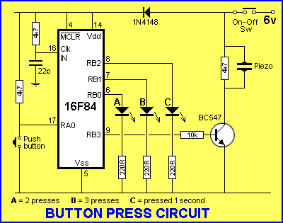
The program must decide if the button has been pressed two times, three times
or for 1 second.
LED A indicates 2 presses,
LED B indicates 3 presses and
LED C indicates 1 second.
The common feature with all these is timing. The program detects when the
button has been released and works out if it has been pressed two or three
times or for 1 second. The simplest method is to poll the button every 50mS (20
times per second) and turn on the appropriate output.
The only additional delay that must be included in the program is a delay of
approx 1 sec after the button has been pushed two times. The program is waiting
for a 3rd push and if this is not received within 1 second, LED B is turned
ON.
All the routines for this circuit have already been covered in this course.
It's just a matter of sitting down and working out how the program will
"run."
This is best done with a flow diagram. This type of diagram will not answer all
your problems but it will give you some idea of the sub-routines needed and
will help you start with the program.
Here is the FLOW DIAGRAM:
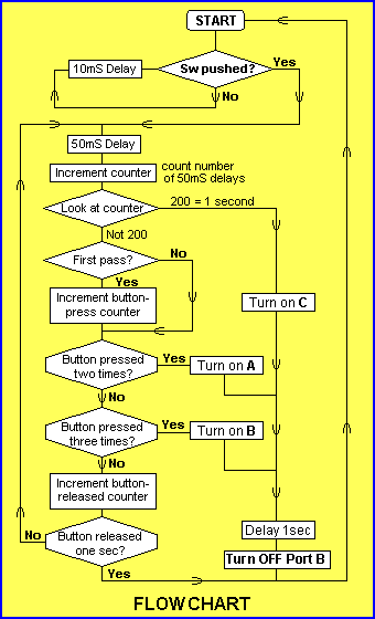
A FLOW CHART does not show all the programming needed to carry out the
operations but it serves as a starting point.
From the Flow Chart above you can see how the micro will progress through the
program as soon as it comes out of a loop that looks at the push-button in the
"Sw pushed?" loop.
This loop is placed in the Main routine and provided it is accessed
regularly, it will not miss a button-press. It has been placed in
the Main routine so you can add to it or incorporate it into other
programs.
The program includes a Beep routine to indicate the button has been pressed.
Most of the complexity of the program is the "house-keeping." This is
keeping track of the number of times the button is pressed. This involves
four files. When the button is pressed, a bit is set in file 1D. This tells the
program the button has been pressed and the button-press counter (file 1F) is
incremented. When the micro loops the program for the second time, it checks
to see if the button-press bit has been set, so it does not increment the
button-press counter. When the button is released, the button-press bit
is cleared and when the button is presses again, the button-press counter is
incremented. In this way the number of pushes is recorded.
Another file for the button (file 1E) counts the number of loops of the program
to identify when the button has been pressed for 1 second - to turn on LED C.
Finally, another file (file 20h) counts the time when the button is not-pressed
and returns the micro to Start. This deals with the possibility of the button being
pressed only once.
You have to deal with all possible button-presses, so the program does
not "lock-up."
The most difficult decision is detecting two presses for LED A.
The program detects two presses then waits 0.75sec for another press. If the
third press is not detected within 0.75sec, LED A is illuminated.
Here is the program:
;PBA_F84.asm
;Project:Push Button
List P = 16F84
#include <p16F84.inc>
__CONFIG 1Bh ;_CP_OFF & _PWRTE_ON
& _WDT_OFF & _RC_OSC |
Start
SetUp
Beep
Beep1
Beep2
Delay1
Delay10
Delay10A
Delay50
Delay50A
LED-A
LED-B
SwPushed
SwPushed1
SwPushed2
SwPushed3
SwPushed4
SwPushed5
SwPushed6
Main
|
ORG 000
BSF 03,5
MOVLW 01
MOVWF 05
MOVLW 00
MOVWF 06
BCF 03,5
CLRF 06
CLRF 1D
CLRF 1E
CLRF 1F
CLRF 20h
GOTO Main
MOVLW 40h
MOVWF 14h
MOVLW 80h
MOVWF 15h
DECFSZ 15h,1
GOTO Beep2
MOVLW 08
XORWF 06,3
DECFSZ 14h,1
GOTO Beep1
RETURN
MOVLW 014h
MOVWF 1C
CALL Delay50
RETURN
MOVLW 0A
MOVWF 1A
NOP
DECFSZ 1B,1
GOTO Delay10A
DECFSZ 1A,1
GOTO Delay10A
RETURN
MOVLW 032h
MOVWF 1A
NOP
DECFSZ 1B,1
GOTO Delay50A
DECFSZ 1A,1
GOTO Delay50A
RETURN
BSF 06,0
GOTO
SwPushed2
BSF 06,1
GOTO
SwPushed2
CALL Beep
CALL Delay50
INCF 1E
MOVLW 0C8h
XORWF 1E
BTFSS 03,2
GOTO SwPushed3
BSF 06,2
CALL Delay1
CLRF 06
GOTO Start
BTFSC 1Dh,0
GOTO SwPushed4
BSF 1Dh,0
INCF 1Fh
BTFSS 05,0
GOTO SwPushed1
BCF 1Dh,0
CALL Delay50
BTFSS 05,0
GOTO SwPushed6
MOVLW 02
XORWF 1Fh
BTFSS 03,2
MOVLW 096h
XORWF 20h
BTFSC 03,2
GOTO LED-A
MOVLW 03
XORWF 1Fh
BTFSS 03,2
GOTO LED-B
INCF 20h
MOVLW 0C8h
XORWF 20h
BTFSC 03,2
GOTO Start
GOTO SwPushed5
CLRF 1E
CLRF 20h
GOTO
SwPushed
BTFSS 05,0
GOTO SwPushed
CALL Delay10
GOTO Main
END |
;Load the
code at address 000
;Select Bank1 to set in/out bits
;Put 0000 0001 into W
;Load TrisA file. Make RA0 input
;Put 0000 0000 into W
;Load TrisB file. Make all lines output
;Select Programming area - Bank0
;Clear Port B of junk
;Clear button-press flag
;Clear 50mS Delays counter
;Clear button-press counter
;Clear button not-pressed counter
;The duration of the beep
;The loop file
;The duration of the High and Low
;To toggle bit3
;Toggle RB3
;Load W with twenty
;Call Delay50 twenty times = 1 second
;Load W with ten to create 10mS delay
;Put ten into file 1A
;Create 1,000 microsec delay = 1mS
;Load W with fifty to create 50mS delay
;Put fifty into file 1A
;Create 1,000 microsec delay = 1mS
;Increment 50mS Delays counter
;Load W with two hundred = 200x50mS = 1sec
;Compare file 1E with 0C8h
;Look at zero flag. Flag = 1 = SAME!
;Turn on LED-C
;CALL 1second delay
;Clear All port B
;First pass of loop for button-press?
;Not first pass of loop
;Set button-press flag
;Increment the button-press counter
;Test for button-press
;Button still pressed
;Clear the button-press flag
;Delay 50mS before re-testing
;Test for button-press
;Button Pressed
;Has button been pressed twice?
;Look at zero flag. Flag = 1 = SAME!
;Load W with 150 for 0.75sec timing
;Compare file 20h with 0C8h
;Look at zero flag. Flag = 1 = SAME!
;Button pressed twice then delay of 0.75sec
;Look at zero flag. Flag = 1 = SAME!
;Button pressed 3 times
;Increment not-pushed file
;Load W with two hundred
;Compare file 20h with 0C8h
;Look at zero flag. Flag = 1 = SAME!
;Button released too long
;Clear the 50mS Delays counter
;Clear the not-pushed file
;Test the input line
;Button pushed
;Button not pushed. Loop again after 10mS
|
|
NEXT
|