|
|

CIRCUIT A
Circuit A shows a 27MHz transmitter circuit without a crystal. The main reason for a crystal is to comply with the strict transmitting laws in most countries. A fairly narrow band has been allowed at 27MHz and to keep within this area, a crystal has been used. Since a crystal is not an expensive component when bought in the millions, manufacturers have included them in their circuits to get instant approval.
However the important reason for using a crystal is to get reliable operation.
When a circuit does not have a crystal, the oscillator is said to be "voltage dependent" or "voltage controlled" and when the supply voltage drops, the frequency changes.
If the frequency drifts too much, the receiver will not pick up the signal.
For this reason, a simple circuit as shown in circuit A is not recommended. We have only included it as a concept to show how the 27MHz frequency is generated.
The two transistors are doing two things at the same time. The second transistor is a self-contained oscillator and it gets its feedback (to oscillate at 27MHz) from the transformer. The main coil is the 8t section and the feedback to the base is 4 turns.
The first transistor is also connected to the second transistor and the two form a low-frequency oscillator in which the first transistor forms the timing for the oscillator and the second transistor provides positive feedback.
The first transistor turns on via the 1M and the transistor sees this as pulling the base "down." The collector of Q1 pulls the base of Q2 "up" and Q2 turns ON. This causes current to flow in the 100R and the voltage on the right side of the 6n8 falls. The capacitor tries to make the left side fall too and turn on the first transistor even more. This happens until Q1 cannot turn on any more and the 6n8 charges a little more. This turns off Q! a small amount and the to transistor begin to turn off.
The frequency of the tone is determined by the value of the 6n8. All the time that this is happening, Q2 is oscillating at 27MHz and it is just being "DC shifted" up and down.
The tone consists of short spikes, unlike the tone produced by Circuit B, which has an almost even mark-space ratio.
The second circuit comes from a GS Remote Control Car. It does not have the 2k2 current-limiting resistor and you can experiment to see which circuit consumes the least current and has the best range.
See GS Remote Control Car Receiver Circuit below.
(receiver for this circuit HERE)
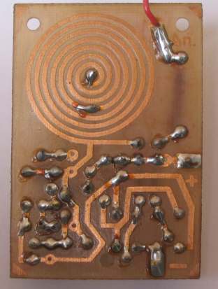
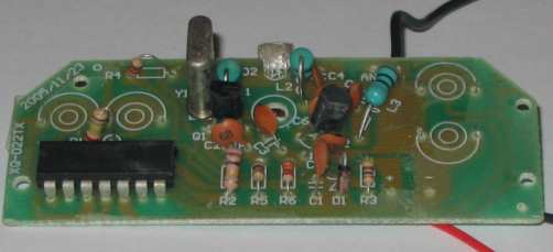
Circuit A was quickly constructed on a piece of copper board to act as
an earth plane and to make
sure it worked and to see if any improvements could be made. If a
circuit works well in an open format such as this, you can be sure it
will work better when constructed on a printed circuit board where the
circuit is much "tighter" and the impedances are lower. The layout above
is called a "Birds Nest" and allows rapid modifications to be made and
you can touch the parts to see if your hand capacitance changes the
frequency or stops the circuit working.
HOW THE CIRCUIT WORKS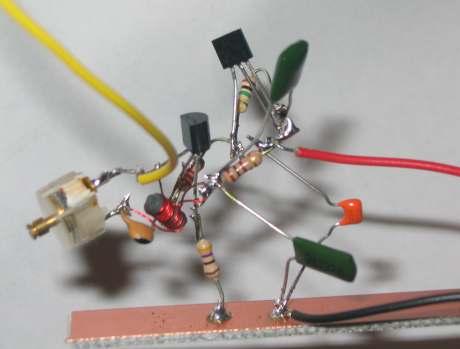
Circuit A - Birds Nest
Circuit B also produces a tone. But this time two transistors are
used in a multivibrator arrangement, in which one of the transistors is
used to turn the third transistor on and off.
Circuit A is a very efficient and clever circuit and requires less
components. That's why you must study all types of circuits before
producing your own design as simplicity is the secret to success.
The tone is used by a receiver to
determine the signal is coming from the chosen transmitter. The
receiver can have a detector stage to detect the exact frequency or
the tone can be used to change the state of a stage. This is called
integration, where the energy from the pulses from the tone are added
together to charge or discharge a capacitor.
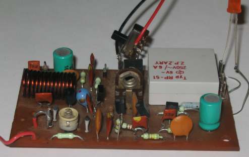
Circuit B comes from a Russian design, and it uses Philips
transistors!
We tested the output with our Field Strength Meter MkII and found it had a good
output. Details of Field Strength Meter MkII are discussed below.
But the circuit has some poor features. The poorest feature is the
printed-circuit coil. This type of coil has the lowest value of "Q." "Q"
is the name for the "Quality factor" for a coil and it effectively
determines how much amplitude you will get. Quite often the output of a
coil will be higher than the voltage being supplied to it and this gives
the value of "Q."
The other poor design is turning the emitter of the third transistor on and off. A better
solution is to drive the base as has been done in Circuit A. This allows full voltage to be applied to
the stage.
Here is the circuit:
Circuit B consists of two blocks. Block 1 is a multivibrator and this
has an equal mark/space ratio to turn the RF stage on and off.
We have covered the operation of a multivibrator in the electronics
course on Talking Electronics website, in the subscription section.
The only thing you have to know for this circuit is the fact that the
middle transistor turns on for 50% of the time and the voltage between
the collector and emitter drops to less than 0.3v This voltage is too
low for the third transistor to operate and thus the RF stage is turned
off.
The second building block is the RF oscillator.
The actual operation of the stage is very complex and beyond the scope
of this discussion. However some of the points are as follows:
The feedback to keep the stage operating is provided by the 27p
capacitor.
The frequency-producing items are the coil (made up of the full 7 turns)
and the 47p air trimmer. These two items are called a parallel tuned
circuit. They are also called a TANK CIRCUIT as they store energy just
like a TANK of water and pass it to the antenna.
The base is kept rigid by both of the 4n7's. In other words, the base
does not move.
The stage is turned on by the 22k and 15k voltage dividers. A voltage of
5v is produced at the join of these two components. The voltage on
the emitter will be 0.6v
lower.
This will cause current to flow in the 220R and also in the 3t winding.
These turns will produce magnetic flux that will cut the other 4 turns
and produce a voltage in them. This energy will pass to the antenna and
some of it will charge the 47p and in doing so the voltage on the
collector will reduce. This voltage will be passed to the emitter via
the 27p and this will turn the transistor on more. This will continue
until the coil cannot produce any more voltage and the transistor will
begin to turn off. The collapsing magnetic flux in the 3 turns will cut
the 4 turns and produce a voltage in the opposite directions and the
other half of the cycle will be produced.
The frequency of the circuit is adjusted by the 47p air trimmer.
RECEIVERS
The following receiver matches up with Circuit B above.
HOW THE CIRCUIT WORKS
27MHz Receiver
The circuit consists of a number of
building blocks and these can be identified when a capacitor separates
one stage from another.
The first stage is actually a 27MHz oscillator with a very small output
due to the 4k7 resistor connecting the stage to the positive rail. This
allows very little current to enter the stage and the transistor
operates on a very "delicate basis."
When a circuit is oscillating and delivering a signal to the air
surrounding the antenna, any other signal entering the same surroundings
will cause an interference with the generated signal and the circuit
will find it more-difficult to deliver a signal, especially when the
signal has the same frequency. This will cause the
voltage on the collector of the transistor to alter and produce a signal
that can be passed to further stages of amplification.
The 5v1 zener is designed to keep the voltage on the first stage
constant as the transistor is oscillating and is a voltage-controlled
oscillator.
All the components in the first stage are designed to make it very
sensitive to detecting a signal.
Normally, all the surrounding signals upset the clean sine-wave produced
by the stage and the result is a lot of "noise" or "hash" or
"background
noise" at the "pick-off" point.
If the 27MHz signal produced by a transmitter contains a tone, this tone
will appear at the "pick-off" point along with the hash.
The frequency of the hash is fairly high and on the second stage there
are three components to remove it.
The first is the 1k5 resistor. This, in combination with the 47n, has a
slight effect.
Next, the 15n between base and ground will remove high frequencies. And
finally the 2n2 will send any amplified signal back to the base for
cancellation. This capacitor has a greater effect on canceling high
frequencies.
The third and fourth stages also remove some of the high frequency
component of the signal and the result is a clean signal with only the
tone appearing on the base of the fourth transistor.
This signal has a large amplitude and will turn the transistor on fully.
The transistor normally sits with the collector very close to rail
voltage due to the low value of collector resistor and this means
transistor Q5 is not turned on.
The 47u gets charged via the 1k5 resistor and the relay is not
energised.
When the fourth transistor sees a tone, it turns on at the frequency of
the tone and this puts pulses of short-circuit across the 47u and it
rapidly discharges.
As it discharges, the voltage on the collector drops and this turns ON
Q5 to operate the relay.
When the tone stops, the 47u rapidly charges via the 1k5 and the relay
switches off.
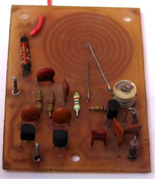
The photo below shows a switch added to the PC board and a LED connected
to the output of the relay to test the receiver.
The pot in the centre of the board adjusts the sensitivity of the
receiver.
Receiver for transmitter in Circuit B
The relay can be latched ON via the
following circuit but it cannot be turned on remotely. The power has to
be disconnected to release the relay. This is only suitable for a
"one-shot" operation where a device has to be turned on only once.
If a long tone is required to turn on the relay (to prevent false
triggering), the following circuit can be used. The 100u electrolytic
takes about 2 seconds to discharge via the 10k resistor, as the 4k7 adds
to the time-delay, since it is providing charging-current that the
transistor has to overcome.
The following circuit allows a single channel transmitter/receiver to
turn an appliance on and off by sending a short pulse to turn a circuit
on and a long pulse to turn a circuit off.
The circuit above can be added to many different receiver circuits, thus
using only one output to provide an on/off function. 
(Latching Circuit)
This is handy when you cannot see the result of your operation. A simple
toggle operation is not suitable as you do not know the state of the
output at the start of the operation.
By sending a long pulse, you definitely know the output will be OFF and
you can then control the output remotely.
A short pulse is less than 0.25 sec and a long pulse can be any length
longer than 1 second.
These times can be adjusted by changing the value of the components.
When a short tone is received, the lower 47u discharges and pulls the
base of the BD136 towards the 0v rail and turns the transistor ON. This
activates the relay and the contacts take the 4k7 to the 0v rail to keep
the transistor ON.
During this time the top 47u charges via the 100k but not enough voltage
appears across it to turn on the BC557 transistor.
If the tone appears for a long period of time, the top 47u charges and
turns on the BC557 and the voltage between the emitter/collector
terminals is less than 0.3v. This voltage is too low for the BD136 to
remain on and it turns off.
When the tone is turned off, the BC557 remains on for 1 second and then
turns off.
The circuit is then ready to be activated again. 
The purpose of presenting a number of circuits is to show the basics of
how this type of circuit works.
The secret behind a receiving circuit is to create a "front-end" that is
actually oscillating at the frequency to be detected and it
transmits a very weak signal out the antenna. When a signal of the same
frequency is detected by the front-end it takes more current and less
current according to the tone being carried by the 27MHz signal (as the tone is
actually increasing and decreasing the strength of the signal). This
amplitude appears on the output of the "front-end" and is
picked off via the 39n capacitor. It is then amplified by two stages.
The 10n on the collector of the second transistor is designed to remove
the "hash" or background noise. This signal then turned into a DC voltage
by charging a 1u electrolytic and the negative portions of the signal
are removed by the diode. When no signal is detected, the transistor is
not turned on and the motor operated in the forward direction. A signal
turns on the transistor and the other two transistors in the
half-bridge are turned ON to reverse the motor.
We have already discussed the operation of a circuit such as this, with
a multivibrator and RF oscillator. The only new feature is the
arrangement for producing two different tones.
The circuit for the receiver has not been taken off the printed circuit
board, however a general circuit is provided in the datasheet for the IC
and this has been reproduced above.
The receiver using the RX-2 chip:
2.
If you want a more sensitive detector, use
.
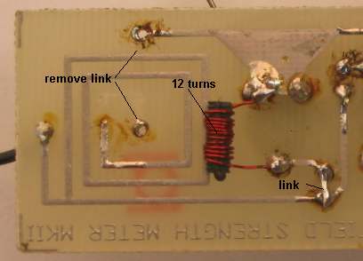
3. Field Strength Meter MkII
can be modified to detect transmitters in the range 27MHz to 49MHz
by placing a 12 turn inductor on the bottom of the board. This is made
by winding 12 turns of 0.25mm wire on a 2mm x 5mm ferrite slug.
The 47p capacitor in series with the 47p air trimmer is "shorted out"
under the board as can be seen in the photo above. The link to the coil
on the board is removed so that it effectively comes out of circuit. No
other parts on the board are changed. 4. You can buy a Remote Control Car or Walkie Talkie to get a
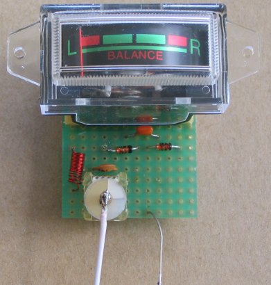
transmitter and receiver. 5. Field Strength Meter MkIII uses a 600 ohm movement
(1mA FSD) but almost any movement will be suitable.
The 100p and 18 turn coil form a tuned circuit that oscillates at a
particular frequency. The frequency at which the components oscillate is
changed slightly by the 47p air trimmer. The signal then passes into a
2-diode rectifier with one diode passing the voltage to the meter and
the other diode discharging the 47p on the negative half of the
waveform. The 100n across the meter stores and smoothes the voltage for
the 1mA (Full Scale Deflection) movement.
(transmitter for this circuit HERE)
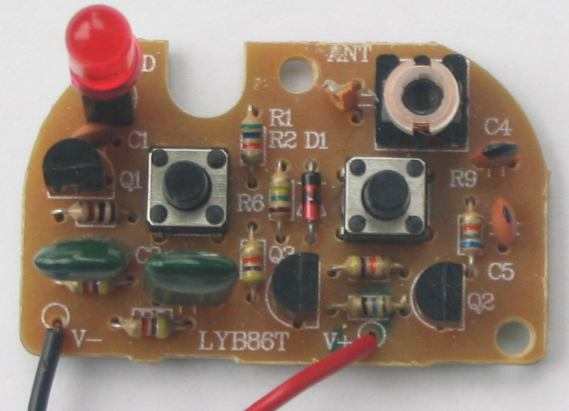
The next circuit is a 2 channel transmitter.
This circuit does not use a crystal but has a clever feature of using
the two push buttons to turn the circuit on when it is required to
transmit.
Click HERE for RX-3 IC datasheet .pdf
The receiver requires a 1kHz and 250Hz tone for the forward and reverse
outputs. The frequency of the multivibrator is determined by the value
of resistance on the base of each transistor. The multivibrator is
driven directly from the supply with the forward button and via a 150k
for the reverse frequency.
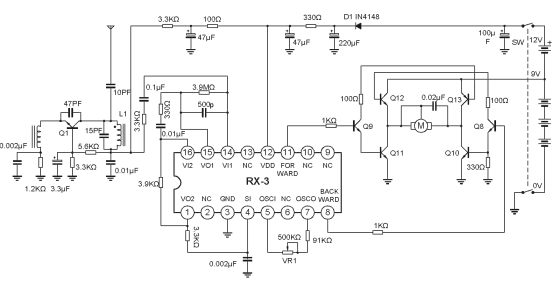
Both output of the chip cannot be HIGH at the same time as this will
destroy the transistors in the "H-bridge."
For the forward direction, the forward output is HIGH and this turns on
Q9, Q11 and Q13.
For the reverse direction, the backward output is HIGH and this turns on
Q8, Q10 and Q12.
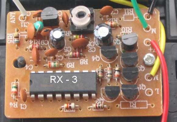
This toy remote control car cost less than $8.00, but a defect in the
design was noted.
The motor would reverse approx every 2 minutes for a short
period of time, even though no transmitter button was pressed and
the motor would operate in bursts when the car was distant from
the transmitter. The interference was not from any electronic device in
the home as the receiver was taken to an open space and it still
faulted. The first transistor was removed and the fault did not occur.
This means the RF transistor is generating a fault that is detected by
the chip to turn on an output.
This could be due to the
chip detecting a frequency of 1kHz or 250Hz to turn on an output. Random
noise could be in this range and that's why the RX-3 receiver chip is
unreliable.
Maybe that's why the car was $8.00!
Another point of comparison: the RX-3 receiver circuit consumed 4.4mA at 4.5v, while the RX-2B
receiver consumed 0.7mA at 3v.
4 CHANNEL TRANSMITTER
This circuit uses the TX-2B RX-2B chipset discussed on
the previous page. The chip has 5 channels and the circuit uses 4.
Click HERE for TX-2B RX-2B chipset datasheet .pdf
TX-2B circuit on datasheet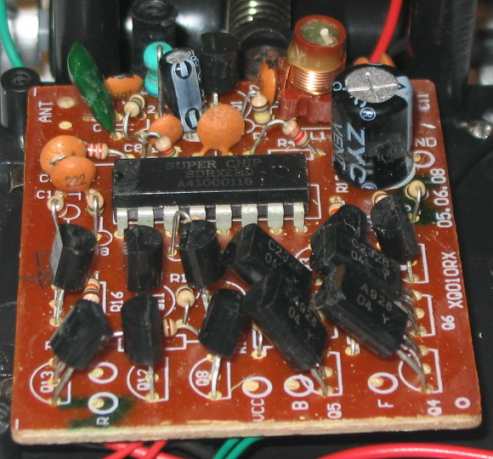
RX-2B circuit on datasheet
FIELD STRENGTH METERS
There are five pieces of test equipment you can buy or build to test the
output of a transmitter.
1. LED Power Meter, Detects RF
energy and indicates the result on a multimeter set to 2v or 10v scale.
2. Field Strength Meter MkI.
FSM MkI detects RF energy and indicates the result on a multimeter set
to 10v scale.
3. Field Strength Meter MkII.
FSM MkII has a scale 26MHz to 50MHz. By turning a pointer connected to
an air trimmer, the frequency of a transmitter can be determined.
4. Field Strength Meter MkIII - uses a 600 ohm Balance Movement.
5. 27MHz Walkie Talkie - purchase from a toy store.
When working with a transmitter, the first thing you will want to do is
determine if the transmitter is producing RF.
Talking Electronics has three kits for this.
1. The LED Power Meter costs
less than $2.00 and connects to a multimeter set to 2v or 10v range or
you can use the 0.5mA range. It
connects directly to the antenna of the transmitter and a LED
illuminates if the transmitter is producing more than about
30milliwatts. If the transmitter is producing less than 30mW, the needle
on the multimeter will deflect, but the LED will not illuminate.
The photo below shows the LED Power Meter connected to a mini
Multimeter. These are available from "$2.00 shops" for less than $10.00
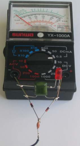
LED Power Meter connected to a
mini multimeter
The multimeter in the
photo has a sensitivity of 2,000 ohms per volt.
This means the resistance inside the meter is 20,000 ohms when the
pointer is on the 10v scale.
This type of meter is called a low sensitivity instrument and is
ideal for the job we are doing.
If a high impedance instrument is used, it can pick up stray RF and
produce a false reading.
A high impedance instrument can be 20,000 ohm per volt, 50,000 ohms
per volt or 100,000 ohms per volt (commonly called a FET meter.)
Digital multimeters can have higher input impedances.
Once you know a transmitter is producing RF (a signal), you can tune it
to a particular frequency.
To do this you will need Field Strength Meter MkII.
When FSM MkII has been modified as shown below, it can be calibrated.
This will allow you to set the frequency of any transmitter that does
not use a crystal.
To detect a tone from a transmitter, use a 27MHz or 49MHz Walkie Talkie.
The tone will be heard in the speaker.
FIELD STRENGTH METER MkII Modification
You will need a transmitter with a crystal to calibrate the Field Strength Meter.
You can then use the FSM to adjust any of the transmitters that do not
have a crystal.
Field Strength Meter MkII can also be used to determine the relative
output of each transmitter by using the same length antenna on each
transmitter and holding FSM MkII at the same distance from the
transmitter. The three LEDs on the PC board will show the relative
signal strength.
The size and shape of the coil is extremely important and the photo
shows
slight stretching on the last turn to peak the circuit.
This circuit shows the amazing ability for two passive components to
"amplify." The 100p and 18 turn coil form a TUNED CIRCUIT and when
the incoming frequency is exactly the frequency at which these two
components oscillate, the output rises considerably.
If you have transmitter, you can set up the circuit to detect an exact
frequency by winding the 10cm tinned copper wire antenna around the
antenna of the transmitter. Each centimetre gives about 2p of
capacitance and this is sufficient to connect the two together "RF
wise."
The circuit requires 18 turns but if you add one turn, you can stretch
the coil to get the circuit to peak then remove it later.
Finding the resonant frequency of the coil and capacitor is a very
difficult thing to do as the peak comes and goes in less than 1/10mm of
stretching the coil.
In addition, you cannot touch the coil or be anywhere near the circuit
when making the adjustments as you body completely "soaks away" the
energy.
You have to use a plastic knitting needle and move the end turn very
slowly while watching the meter.
You will see it move from zero to more than half way as the adjustment
is made.
You now have a piece of test equipment that will indicate when a
transmitter is operating at an exact frequency.
If you want to know if the transmitter is producing RF, you will need
Field Strength Meter MkI as it purely detects RF.
Talking electronics
has designed a PC board with Field Strength Meter circuit to
detect 27MHz. Most of these transmitters are very low power and getting
a reading on a meter (actually called a "movement") is very difficult.
To help get a reading we have added a transistor amplifier.
The result is:
Click
HERE to go to the project.
18/9/14