
|
Page 1
WHAT IS AN OP-AMP?
Go to:
P2 P3
P4(data table)
A very good discussion on
Op-Amps from Element 14
Quiz from Element 14
![]()
Before we describe anything technical, let's see one in action.
An op-amp can be connected to a single voltage rail (called UNIPOLAR
SUPPLY - 0v to Vcc) or a dual voltage rail (called BIPOLAR SUPPLY
+/-Vcc).
When connected to a single voltage rail, the output can go from 0v to
approx full rail voltage.
The OP-AMP has two inputs. A "+" input for non-inverting and "–" for
inverting. When the "+" input is a few millivolts higher than the "–"
input, the output goes HIGH. It's that SIMPLE.
Study the animation below:

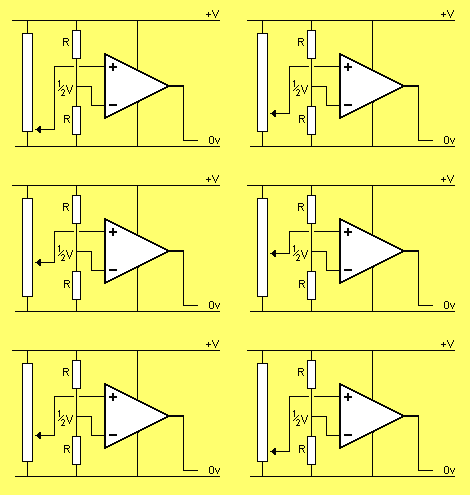
If the "–" input sits at half rail voltage via two equal-value resistors, the "+" input must go above ½V for the output to go HIGH, as shown in the animation below:
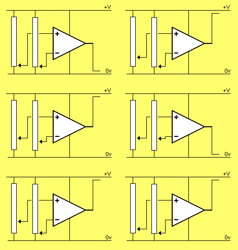
The "–" input can control the output as shown in the animation below:
From the animations above we have shown two things:
1. The "+" input must be higher that the "–" input for the
output to be HIGH.
2. A small increase in voltage on the "+" input (above the "–"
input) will change the output from 0v to approx full rail voltage. This
represents HIGH GAIN or AMPLIFICATION.
VOLTAGE FOLLOWER |
In this arrangement the OPerational AMPlifier is called a BUFFER and has unity gain.
The OP-AMP works like this:
As the "+" input rises, the output rises.
Normally the output would rise to rail voltage, but since it is connected to the "–" input, it will always be a few millivolts below the "+" input.
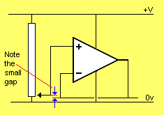
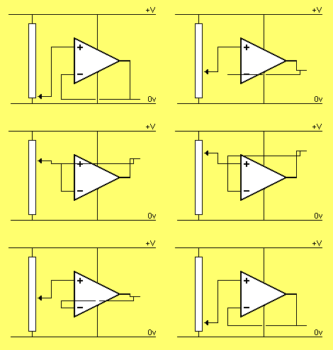
Note: the output follows the input
The OP-AMP in the arrangement above has UNITY GAIN (gain = 1).
GAIN |
In the following animation, the OP-AMP has a gain of 2.
For a gain of 2, the two resistors on the inverting input are EQUAL VALUE. The actual value of resistance is not important. It can be 10k to 100k, for example.
The point to note is this: The voltage at the mid point of two equal-value resistors is half the delivered voltage. We have already seen from the animation above that an OP-AMP needs a voltage on the inverting input that is almost equal to the non-inverting input to produce the "following effect." Thus, to get this voltage on the "–" input, the output of the OP-AMP must be TWICE the voltage on the "+" input.
This is shown in the animation below:
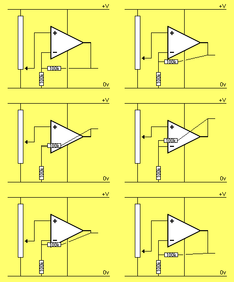
From the animation above, you can see how to turn an OP-AMP into an
AMPLIFIER.
The gain of an OP-AMP is determined by the ratio of resistors R1
and R2.
Here is an OP-AMP with a gain of 5:
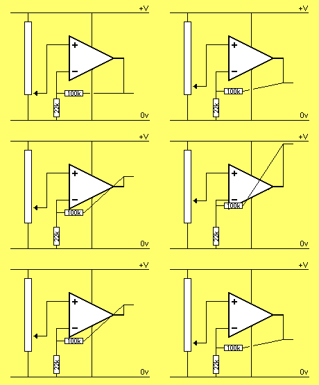
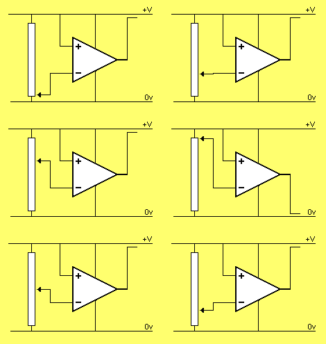
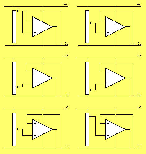
If the "+" and "–" inputs are reversed, the OP-AMP will not work (or produce a valuable output) as shown in the following two animations:
 |
 |
The above animations show how to amplify a signal with an OP-AMP.
We will now cover some technical details.
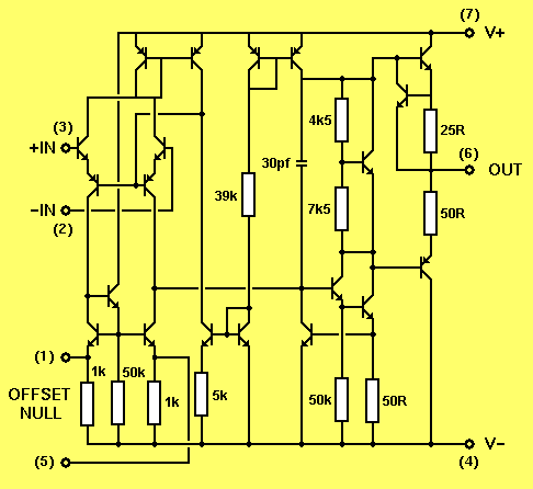
OP-AMPs contain a number of transistors (25 or so) but the internal
workings do not concern us. The only thing we need to
know is how to get it to operate.
An OP-AMP is represented as a "block" in a circuit diagram with two
inputs and an output:
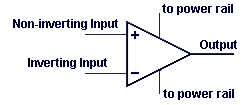
An increasing signal (voltage) on the Non-Inverting Input "+" will
create an increasing signal on the output.
An increasing signal (voltage) on the Inverting Input "–" will create
an decreasing signal on the output.
An OP-AMP can be connected to a single voltage rail (called UNIPOLAR
SUPPLY) or a dual voltage rail (called BIPOLAR SUPPLY) as
shown in the diagrams below:
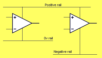
An OP-AMP connected to a single voltage rail will produce an output
from 0v to approx rail voltage.
An OP-AMP connected to dual rails will produce an output from –V to +V
as show below:
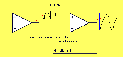
You need to know if an OP-AMP is connected to a single rail or dual
rails as this will determine the type of signal it is capable of
producing.
SPLIT RAILS
or DUAL RAILS -
also called BIPOLAR SUPPLY can be produced as follows:
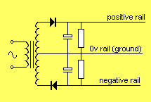
This will allow the output of the OP-AMP to change from negative to positive as shown in the animation below:
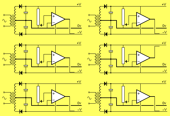
The positive and negative rail is normally equal in magnitude
however if they are not equal, the OP-AMP will produce waveforms equal
to size of each rail.
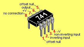
One of the cheapest and most-popular OP-AMP is the 741.
The pinout for an LM741 is shown below:
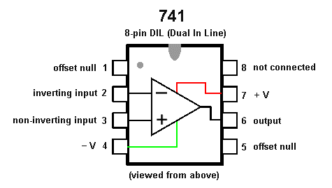
The basic parameters for a 741 are:
Rail voltages : +/- 15v DC (+/- 5v min, +/- 18v max)
Input impedance:
approx 2M
Low Frequency voltage gain: approx 200,000
Input bias
current: 80nA
Slew rate: 0.5v per microsecond
Maximum output current:
20mA
Recommended output load: not less than 2k
The following diagram shows the 741 in a typical audio circuit:
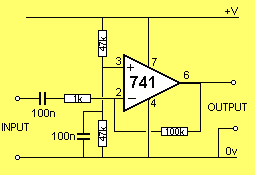
From the discussion above we can see how the circuit above sets its
operating conditions.
1.
The "+" input sits at half-rail voltage via the two 47k voltage-divider
resistors.
2.
This makes the output go HIGH and the voltage on the "–" input
increases until it is just below the "+" input. (The "–" input cannot
rise above the "+" input as this will make the output of the OP-AMP go
LOW).
3.
The end result is the OP-AMP is "half-turned-on" and any
increase or decrease in voltage on the
"–" input will make the output go LOW or HIGH.
Don't forget: the output will move in the opposite direction to the
voltage applied to the "–" input.
HOW DOES THE OP-AMP AMPLIFY? |
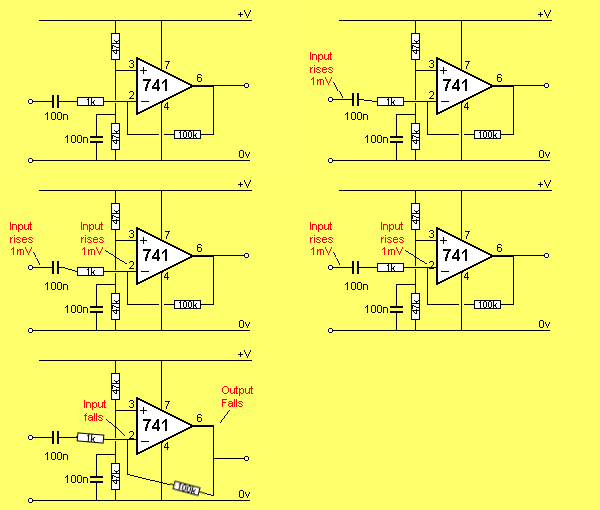
Suppose the voltage on the input rises 1mV.
This rise will pass through the 100n capacitor and appear on the "–" input as a 1mV increase.
The OP-AMP will amplify this signal 100,000 times and the output will try to FALL as much as 100v - but the voltage-divider resistors come into operation as follows:
The output will fall and this will be passed to the "–" input via the 100k resistor. As soon as the output falls 100mV, the voltage seen by the "–" input will be 1/100th of 100mV or 1mV. Thus the 1mV produced by the signal will be negated by the effect of the output dropping.
The effect is slightly less than 1mV being fed back to the "–" input and the output drops 100mV.
The "–" input sees about 100th of 1mV and the output drops 100mV.
The following animation shows (in slow-motion) how the voltages flow though the OP-AMP:
Go to: P2