|
Page 2
OFFSET NULL
NON-INVERTING AMPLIFIER
INVERTING AMPLIFIER
THE OP-AMP AS A VOLTAGE FOLLOWER
THE OP-AMP AS A COMPARATOR
Go to:
P1
P3
P4 (data)
![]()
Many OP-AMPs have two pins labeled OFFSET NULL. When both inputs
are connected to the same voltage, the output should be
zero. If the project requires a zero output under these conditions, the
OFFSET NULL should be adjusted by adding a 10k pot between the Offset
Null pins with the centre of the pot connected to 0v.
By adjusting the pot, the output will produce 0v. 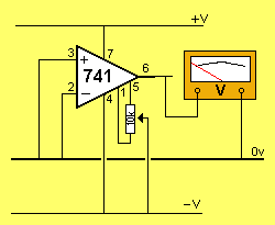
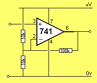
The circuit shows an OP-AMP connected as a NON-INVERTING AMPLIFIER:
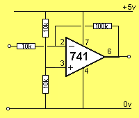
The circuit shows an OP-AMP connected as an INVERTING AMPLIFIER:
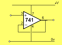
The circuit shows an OP-AMP connected as a VOLTAGE FOLLOWER:
The OP-AMP can compare two signals (voltages). This is called a
COMPARATOR or DIFFERENTIAL AMPLIFIER (amplifies the difference
between two signals).
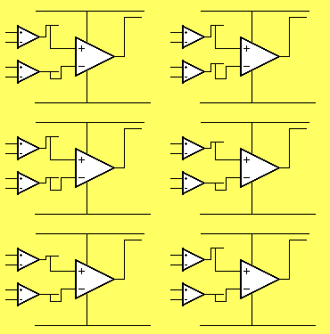
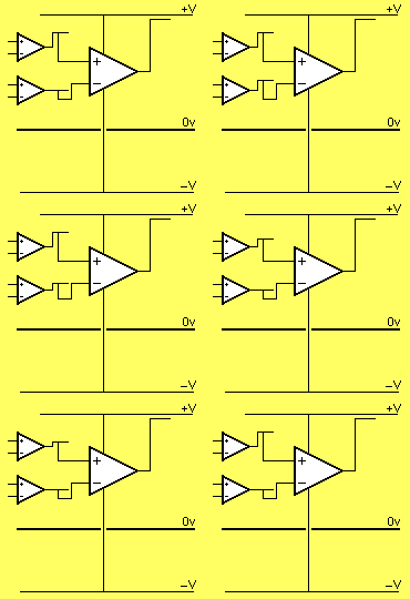
There are two arrangements - connection to a single rail or dual rails. The
animations below show the output for each configuration:
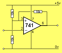
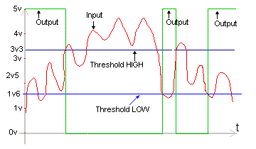
When the input of the Schmitt Trigger is LOW, the output is HIGH.
As the input rises, nothing happens to the output until the input is 3v3.
This is the voltage on the
"+" input due to the effect of the three 10k resistors. These 3
resistors form a voltage divider with two 10k resistors connected to the
5v supply and one 10k resistor connected to 0v.
When the "–" input is 3v3, the output of the OP-AMP goes LOW
and it remains LOW until the input falls to less than 1v6. The 1v6
voltage on the "+" input is produced by the three 10k resistors. When the
output is LOW, one 10k resistor is connected to the 5v supply and two
resistors are connected to the 0v rail. This produces 1v6 on the "+"
input.
The purpose of a Schmitt Trigger is to detect and respond to a signal
that rises and falls a large amount - in other words it has "large
excursions."
There are also signals that rise and fall very slowly - such as a photo
transistor detecting daylight.
During the detection process, the output will rise and
fall slightly during the morning light and the change from one level to the other will
cause the project to turn on and off.
This is unwanted. The Schmitt trigger will
produce an output when a definite condition is met and will not change
until the daylight is reduced considerably.
PRACTICAL CIRCUITS |
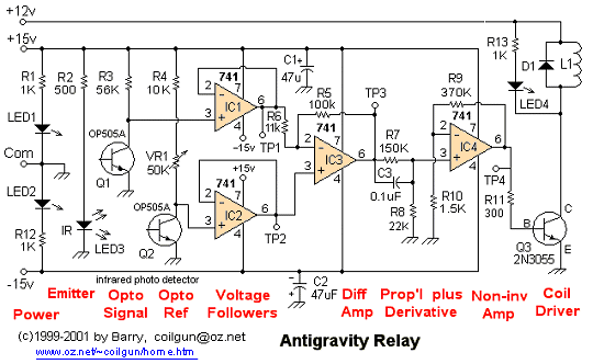
TIMER
When the push-button is pressed and released, the LED illuminates after a period of time. The heart of the circuit is an OP-AMP configured as a comparator. The operation is as follows. When the voltage at "+" input is less than the voltage at "–" input, the output at the output is LOW. When voltage at "+" input is more than the voltage at "–" input, output is HIGH. It is usual to hold the voltage at "–" input at a particular voltage, known as the reference voltage, and vary the voltage at "+" input to obtain a particular function. The two 10k resistors connected in series form a voltage divider, the voltage at the mid-point being 4.5v
The 500k pot sets the time for the 2200u to charge above 4v5. The 1k stop-resistor prevents a short-circuit if the pot is set to minimum resistance and the button is pressed.
Pressing the switch resets the circuit.
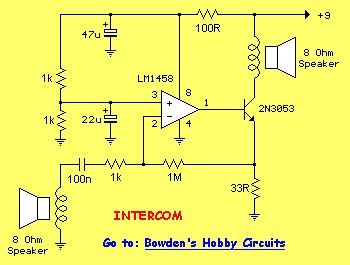
SIMPLE INTERCOM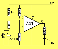
A simple intercom can be built around an OP-AMP:
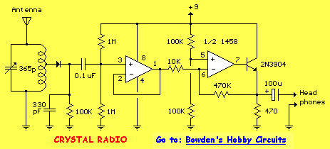
CRYSTAL RADIO
A simple amplifier can be added to a crystal set with an LM1458 OP-AMP:
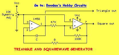
TRIANGLE AND SQUAREWAVE GENERATOR
The following circuit shows a simple triangle/squarewave generator using a common
1458 dual op-amp to produce very low frequencies to about 10 KHz. The time interval for one half cycle is about R*C and the outputs
will supply about 10mA. Triangle amplitude can be
altered by adjusting the 47k resistor and waveform offset can be removed
by adding a capacitor in series with the output.
PRICES
Here is a list of OP AMPS from FUTURELEC with prices and links for each device:
| CA3130E | CMOS Operational Amplifier | $1.10 |
| CA3140E | Bi-CMOS Operational Amplifier | $0.69 |
| CA3401N | Quad Amplifier | $0.65 |
| LF347N | Quad JFET Input Op Amp (Wideband) | $0.75 |
| LF351N | BiFET Op Amp | $0.69 |
| LF353N | Dual BiFET Op Amp | $0.55 |
| LF355N | JFET Input Op Amp Low Supply Curr. | $0.75 |
| LF356N | JFET Input Op Amp | $0.75 |
| LF357N | JFET Input Op Amp (Wideband Dec.) | $0.90 |
| LF398N | Sample and Hold Circuit | $1.79 |
| LF411CN | Low Offset Drift JFET Input Op-Amp | $1.10 |
| LF412CN | Low Offset Drift JFET Input Dual Op-Amp | $1.30 |
| LM10CN | Op Amp and Voltage Reference | $4.95 |
| LM1458N | Dual Operational Amplifier | $0.35 |
| LM2902N | Low Power Quad Operational Amplifier | $0.65 |
| LM301H | Improved Op Amp | $2.95 |
| LM301N | Improved Op Amp | $0.65 |
| LM308N | Precision Op Amp | $2.30 |
| LM310N | Non-Inverting Op Amp | $1.95 |
| LM318N | Precision Hi-Speed Op Amp | $0.79 |
| LM324N | Low Power Quad Op Amp | $0.30 |
| LM3403N | Quad Operational Amplifier | $0.85 |
| LM348N | Quad 741 Op Amp | $0.45 |
| LM358AN | Low Power Dual Op Amp | $0.45 |
| LM358N | Low Power Dual Op Amp | $0.35 |
| LM725CN | Instrumentation Op Amp | $2.50 |
| LM733CN | Differential Amplifier | $0.79 |
| LM741-14N | Operational Amplifier | $0.35 |
| LM741CH | Operational Amplifier | $1.95 |
| LM741CN | Operational Amplifier | $0.25 |
| LM747CN | Dual 741 Operation Amplifier | $0.95 |
| LM837N | Low-Noise Quad Operational Amplifier | $1.95 |
| LMC660CN | CMOS Quad Op Amp | $2.05 |
| NE5532 | Dual Low-Noise Operational Amplifier | $0.55 |
| NE5534 | Low Noise Operational Amplifier | $0.75 |
| OP07 | Ultra Low Offset Voltage Op Amp | $0.90 |
| RC4136N | Quad Operational Amplifier | $0.85 |
| TL062CP | Low-Power JFET Op Amp | $0.40 |
| TL064CN | Low-Power JFET Input Op Amp | $0.95 |
| TL071CP | Low Noise JFET Op Amp | $0.50 |
| TL072CP | Low Noise JFET Dual Op Amp | $0.55 |
| TL074CN | Low Noise JFET Quad Op Amp | $0.80 |
| TL081CP | JFET Input Op Amp | $0.49 |
| TL082CP | JFET Input Dual Op Amp | $0.60 |
| TL084CN | JFET Input Quad Op Amp | $0.55 |
Go to: P3
