|
THE POWER SUPPLY |
TESTING A POWER SUPPLY
One of the most difficult things to do is test the maximum current capability of a power supply.
The easiest thing to do is to connect it to a project and see if it operates correctly, but of you are designing a power supply for general use, you will need to know its capabilities.
There are 4 important features (parameters) you need to check:
1. The output voltage
2. The ripple
3. The current capability, and
4. The maximum short-term current.
There are two ways to test a power supply:
1. A Dynamic load - such as an amplifier, computer etc.
2. A Static Load - also called a DUMMY LOAD.
We will now cover these 5 things:
MEASURING THE OUTPUT VOLTAGE:
You can measure the output VOLTAGE of a power supply with a multimeter as show in the following diagram:
Measuring the output
voltage of a power supply.
The power supply should be connected to a project. The reading on the
multimeter will give an accurate indication of the rail voltage under
load.
MEASURING
THE OUTPUT CURRENT:
You CANNOT measure the output current with an ammeter:
You cannot measure the output current
of a power supply via this method
The ammeter places a SHORT-CIRCUIT on the output of the power supply and
it will give a false reading.
Some powers supplies will shut down completely and others will
try to drive the maximum "designed-current" through the "short-circuit."
The 3-terminal regulator will get very hot and may be damaged.
The only way to measure the output current is to add a low-value
resistor in the positive line. The resistance must be less than 0.1ohm.
(0R1 brown-black-silver-gold). Two 0R1 resistors in parallel will
produce 0.05 ohms. When 1 amp is flowing, the voltage across the
combination will be 50mV. Use a multimeter switched to mV scale and
measure the voltage across the resistor(s).
The following diagram shows this procedure:
Measuring the output current
There are three reasons why this method is the best:
1. Most multimeters have a fairly high internal resistance (comparatively
speaking) on the amps range and this creates a voltage drop when
measuring current.
2. Few multimeters have a 0-1 amp range. Most have 0-200mA or 0-500mA or
0-10amp. These are not suitable when measuring 0-1 amp.
3. Our method of measurement creates the smallest voltage drop to the
project and thus
the most-accurate reading is obtained.
If the project receives a lower voltage, it will draw a lower current and
thus the reading will be inaccurate. The 50mV drop across the resistors
in the power rail is a known value and you can add a similar value to see
the effect on the current. It will not be a linear decline but our method
will produce the smallest voltage-drop when measuring 0-1amp.
The only way you can damage a power supply is by overloading it. Excess current will heat up the components and they will fail. This can apply to the transformer, diodes, regulator (either chip or transistor) and any fusible resistors. It can also be due to inadequate heatsinking of the regulator.
Overloading can take many forms. A high input voltage will create excess heating.
Excess output current will create over-heating and shorting the output can create excess heating.
Under normal conditions, power supplies do not fail. Electronic components are amazingly reliable and robust. If a component fails more than once, you need to look into the possibility of a spike, excess current or inadequate cooling. A dry joint on the PC board can create excess heating this can damage the component.
MEASURING THE RIPPLE
The ripple on the input or output of a power supply can only be interpreted with a CRO. You must SEE the waveform to understand if and why it is causing a problem. There is no definitive answer to the allowable amount of ripple or "dip" a project will accept without producing a problem. Some circuits are extremely critical and others are not affected at all.
Some digital circuits are tolerant to glitches and dips but audio stages are critical as they are amplifying anything coming from a previous stage.
Any ripple on the power rail will be amplified by subsequent stages. Most stages have a gain of 50 - 100 and two stages will amplify ripple as low as 1mV to produce noticeable hum.
MEASURING THE MAXIMUM SHORT-TERM CURRENT
This is very difficult to measure. You really need to connect the power supply to a project and monitor the output with a CRO. Nothing is more accurate than using a "real" load.
"Instantaneous current" (short-term current) is very important. Many power supplies need to supply 10's of amps or 100's of amps for a very short period.
The output power of most amplifiers is measured for a very short period of time and that's how they arrive at very high wattage values.
To be able to deliver an extremely high current for a short period of time, a power supply needs very high-value electrolytics on the output.
It is the electrolytics that deliver the high current. To determine the capability of a power supply, connect the amplifier and listen to the output. If you are happy with the results, the power supply is doing its job.
If you detect distortion, place the CRO on the power rail.
If the voltage is dipping, add another electrolytic, preferably near the output of the project (near the speakers).
Monitor the improvement.
If the "dipping" is not fixed, the fault may lie in the regulator or the transformer.
You have to decide if the fault has always been present or if it has just developed.
You have to work out if something has to be "fixed" "changed" or "re-designed."
CONNECTING A DUMMY LOAD
A power supply can be tested with a dummy load such as a high-power
resistor or globe.
Most power supplies do not deliver full rated output on a continuous
basis. The demand is constantly rising and falling. A dummy load will put
a constant demand on the supply and you have to be careful not to
over-heat anything.
Once you have decided on the value of the dummy load, you will need a power resistor or
a globe.
There is one major problem with a globe. It requires about 6 times the
normal current to get it to start to glow. This is because the filament
is cold and its resistance is only one-sixth the operating resistance.
Many power supplies will not be able to deliver this current and a globe will not
illuminate. You may think the power supply is faulty - so don't choose a
globe.
The best dummy load for a power supply is a high-wattage resistor. The resistor shown in the diagram will dissipate about 4 watts. Keep it away from the bench-top as it will get very hot and damage any polished surfaces.
Monitor the temperature of the regulator and diodes with your finger to
make sure they do not get too hot.
Make sure you don't keep the dummy load connected too long as it can very
easily overload the power supply.
PROTECTING A POWER SUPPLY
A power supply can be protected from overload (such as a short-circuit) by adding a globe to the positive rail. Make sure the globe has the voltage rating of the rail.
If the globe is rated at 12v/18watt, it will allow up to 1 amp to flow without illuminating and if a short-circuit occurs, the current will be limited to 3 amps.
This safety-feature is handy when experimenting with a high-current power supply (or car battery) as a short-circuit can allow hundreds of amps to flow and completely vaporize fine wires.
FAULT FINDING
Most of the following problems apply to 3-terminal regulator and "power transistor" power supplies. They are the most common and give a number of problems due to the heat developed in some of the components.
The first components to check are always the electrolytics. They play a very big part in the operation of any power supply and can even cause complete failure. The give trouble because energy is passing in and out and this creates heat. The heat produces excess pressure and this forces microscopic particles through the seal and they eventually dry out.
Simply replace or bridge all of them with equivalent values and see if the output improves.
Another common fault is one of the diodes in a bridge breaking down under load. This will produce a lot of hum and the only way to detect it is to measure the temperature with your finger (if the diodes are separate components). A diode that breaks-down under load will measure ok when cold. This is a very difficult to detect if you don't know what to look for. Simply solder 4 diodes across the bridge and see if the fault is fixed.
Another fault is thermal shut-down due to excess input voltage.
If the output voltage of the power supply can be varied, the input voltage will have to be 5v higher than the maximum required output voltage.
When the output voltage is low, the input voltage will be proportionally very high and the power supply will only be able to deliver a low current before thermal shut-down takes place.
NOW - THE LATEST IN POWER SUPPLY REGULATORS . . .
A new type of regulator has just been released on the market.
It is very similar to the 7805 voltage regulator but it has an efficiency as high as 97% and does not require a heatsink.
The following write-up has been provided by Mark Riley of:
Cutter Electronics
5 Highgate Way
Rowville, Vic 3178
Australia
Tel 03 9753 9911
Fax 03 9753 9455
Email: mark.riley@cutter.com.au
Mobile:0417 540 359
Web: www.cutter.com.au PDF Datasheet and selection guide
Everyone knows this situation. A regulated voltage supply is
required.
In itself, there is nothing difficult. Not much board space is
available - no problem. The input voltage supply is unstabilized and
can vary over a wide range. The load is also not exactly steady.
But, what if everything must be accommodated in a small case without
ventilation and no heat-sinking can be used? Or if the regulator
losses must be kept low because the unit is battery powered and you
can't afford to waste precious battery life as heat? Then it already
looks more difficult using the standard off-the-shelf linear
regulator solutions….
The remedy is the new switch-mode converter range from RECOM that
unites both the specifications and the simple application of the
ubiquitous 78xx linear regulators with an extremely high efficiency
of up to 97% to give a minuscule heat generation that avoids all of
the physical and mechanical problems associated with heat sinks and
waste heat transportation.
Just like standard linear regulators, the R-78 series has a drop-out
voltage of 1.5v (this is the difference between the input and output
voltage) and an input voltage range that extends up to 34V:
an input range of up to 7:1!
All of the R-78xx-0.5 series deliver an output current of up to 500mA
and R-78xx-1.0 types with up to 1A output current.
The output voltages are available off the shelf in all of the usual
values of 1.8V, 2.5V, 3.3V, 5V, 9V and 12V as standard.
Non-standard
values can very simply be set in the production by special request.
However, these are not the only advantages of this new converter.
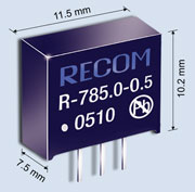
Another attention-grabber is the design: the R-78xx-0.5 is
accommodated in a SIP3-plastic housing with the measurements of only
11.5 x 7.5 x 10.2mm, therefore approximating the footprint of a 78
series linear-regulator in TO220 casing without a heat-sink but with
a clearance gap to the other components on the board. The pin-out is
identical: Pin 1 is the input voltage, Pin 2 the common and Pin 3
the output.
An external trim of the output voltage by means of a fourth pin will
be available as an option in the coming months, as well as a 79xx
series for negative outputs as a counterpart to the analogue 79xx
regulators and implementations for both types in SMD designs.
The RECOM R-78xx-0.5 is continuous short circuit protected and
incorporates a thermal shutdown protection function that switches
off the converter if the internal temperature exceeds 160°C.
The
short circuit protection circuit restricts the input current with a
shorted output to typically 25mA and so helps to avoid further
damage to the supply circuitry during fault conditions. The
operating temperature range is from -40°C to +70°C with full load,
and extends from +70°C to +85°C with a derating to 80% of maximum
load.
The outstanding efficiency of up to 97% comes mainly through the use
of a switch-mode design using the Buck principle.
The 30 years of
experience of RECOM in the design and development of DC/DC
converters has enabled the high specification of this non-isolated
step down converter, in particular the reduction of internal losses
to only a few percent. This switch-mode design inserts itself
seamlessly into the recently introduced RECOM INNOLINE as a
supplement to the non-isolated point-of-load converters with similar
high efficiencies and consequently expands the range for lower power
and miniaturised designs. It presents itself as ideal supplement for
distributed power supplies, where together with the isolating DC/DC
converters from the RECOM POWERLINE and the R-5xxx, R-6xxx and
R-7xxx series from the RECOM INNOLINE, allow supply voltages to be
down-converted as close to the load as possible. Consequently the
entire distributed power supply chain can be supported by RECOM
products.
A frequent and normally justifiable point of criticism concerning
switch mode designs over linear designs is the noise generated on
the outputs as well as the disturbances reflected back into the
input supply. The RECOM R-78xx-0.5 series has a relatively high
operating frequency of around 300kHz which is easy to filter out
internally and so generates very low inherent noise, as the first
EMC-tests confirmed. The switch-mode converter requires no external
components and has typical values of ripple and noise of 30-50mVpp,
which can be even further reduced with external filters. RECOM
recommends that designers who need very low ripple and noise levels
should insert low pass filters: a simple first order LC-low pass
output filter with a corner frequency of approximately 10% of the
operating frequency brings the ripple and noise levels down to 5mVpp
or below.
Also the reflected noise (disturbances that a switch-mode design
generates on its inputs due to its switching frequency) are
inherently very low with the R-78xx-0.5 and can be further
reduced with external filtering of the input supply.
The compromises that a designer must make in order to insert a
switch mode regulator are therefore not great, as in most cases the
standard application with no external components is perfectly
acceptable.
Of course, this switched mode converter won't replace completely the
analogue linear regulator that is used the world over. For one
thing, the price is a deciding factor. A linear regulator can be
bought even in small quantities for a few tens of cents while any
switched-mode solution will always be many times more expensive. But
the total costs needs to be examined: input and output capacitors
are recommended for analogue linear regulators, but these components
are already integrated into the standard switching regulator design
and while the switching regulator needs no heat sink, the linear
regulator requires one in most cases which both uses up valuable
board space and costs money and assembly time.
However, this is not all: presuppose that the circuit is
placed in a small, non-metallic, airtight case - then a heat sink
rapidly loses its effectiveness.
Even a large heat sink will become
useless if air convection and air circulation are blocked. The only
help here is to solve the problem at the root cause. If the
regulator is highly efficient with low internal losses, then almost
no heat is generated that needs to be taken care of. Here, the
switching regulator comes to the fore because it generates so little
waste heat in the first place.
If one now compares the entire costs of a power supply solution -
i.e. switched mode regulator vs. linear regulator + heat sink +
assembly + maybe forced cooling with fans, as well as the further
expenditure for external components, then clearly the cost
relationship is not so unbalanced.
Possible problems in design,
production and assembly of heat-pipe or chilled circuits and the
question of whether it makes any sense at all for sub-15W supplies
are left to the interested reader and will not be discussed further
here.
If all of the above points mentioned above in this article are
considered, even if only some of the aspects apply, then maybe the
alternative of using a switching voltage regulator makes more sense
than at first meets the eye
THE TRANSFORMERLESS POWER SUPPLY
There is another type of power supply. It is called a transformerless power supply.
It is a power supply that does not use a transformer.
Let me say from the start, this type of power supply is very dangerous and can supply only a very small current.
It is not a power supply I suggest for any type of application as the project is effectively "LIVE."
Even though a project may be operating on 5v or 12v, any component on the project will have a potential of 120v or 240v when referenced to earth.
In other words, touching any component in or on the power supply AND the chassis of a radiator or toaster, will result in a shock of 120v or 240v AC.
I should say "up to" 240v (but since we are talking about AC voltages, this voltage is really up to about 340v) and although the transformerless power supply will not deliver the high current that can be delivered from the mains, some transformerless supplies will deliver more than 100mA and it only requires 30 - 50mA to deliver a lethal shock.
The Earth Leakage Detector, fitted to all new homes, trips at 15mA, so you can see the danger of getting a 240v shock!
It may surprise you, but a transformerless power supply is ideally suited to high-voltage applications.
A transformerless power supply can be created using diodes and capacitors that INCREASES the supply voltage. This type of circuit is called a voltage multiplier, and by using multiple stages, the voltage can be doubled, tripled and even increased ten or more times. The end result is a very high voltage and if this voltage is delivered to a pointed conductor, the electronics will stream off and produce an "electric wind." The "electricity" will ionise the air and cause any particles of matter in the air to join together and "drop out."
These circuit are often called "air fresheners."
But we are mainly talking about using a transformerless power supply to
deliver 5v to 12v.
You may think this type of power supply using capacitors is
insulated or isolated from the mains. But this is not so.
A capacitor has a "resistance" - called CAPACITIVE REACTANCE and this
resistance depends on the frequency of the supply. In our case
the frequency is 50 or 60Hz and the capacitive reactance
will be large, however the capacitor will be able to deliver a shock and
in some cases this can be fatal.
If the transformerless supply is connected to the "mains socket" around
the "correct" way, the shock potential will be only 12v, but you cannot
guarantee how the project will be connected.
The above circuits are not actual WORKING
capacitor power supplies.
They are only demonstrating the danger of this type of supply.
In the top diagram, the voltage of the power supply is 12v. But in
the lower diagram, if you touch the 12v line and earth, a totally lethal
shock will result. This is because the "neutral" line has been "lifted
above earth." The "Neutral" is actually just 12v below "Active."
If the project is totally sealed, you can consider using a
transformerless design. Otherwise it is out of the question.
Now we come to the current capability of a transformerless design.
It is the current that determines the "size of the components."
By size I mean the physical size - the wattage dissipating capability.
Transformerless designs using resistors are very inefficient. They waste a lot of energy
and accordingly they get very hot.
Equipment such as amplifiers require a wide range of current. The idle
current may be 10mA but the peak current may be 150mA. This is totally
unsuitable for a resistive transformerless design as the circuit has to
be designed for 150mA and when only 10mA is being taken, the other 140mA
must be wasted.
There are two ways to design a transformerless circuit. One design uses
resistors and the other uses capacitors.
When designing a "capacitor supply" you must consider the "working
voltage" of the
capacitor(s) as well as the current you require.
For a 240v supply, the capacitor should be rated "400v and have an
X2 rating. This means they are suitable for connection directly to the
mains.
There are basically 4 designs as shown in the diagrams below:
Two circuits can be designed around a capacitor as the "current
limiting device" and two can be designed around a resistor as the
current liming device.
The circuits above are only basic examples.
The "Power Supply" is the positive and negative lines above and below the block called the LOAD.
You will need 5 things to create a CAPACITOR SUPPLY:
1. At least 2 diodes and preferable 4 diodes in the form of a bridge.
2. A Current Limiting Resistor to limit the surge current when the supply is first turned on.
3. A Capacitor to deliver (or limit) the current to the "Supply" - the feeder capacitor,
4. A Storage or Filter Capacitor (usually an electrolytic).
5. A Load - generally a resistor
You may also need a resistor called a bleep resistor to absorb the current when (and if) the load is removed.
The diagram below shows these 6 items:
The 6 items of a Capacitor
Power Supply
We will now cover each item.
THE RECTIFIER
The rectifier must be at least two diodes and preferably 4 diodes in
the form of a bridge. A single diode is not suitable as the capacitor
must be charged in one direction via one of the diodes then charged in
the other direction by another diode.
The diodes change AC
waveform to pulses as shown in the diagram below. The full wave
rectifier will allow both the positive and negative excursions to appear
on the output. A single diode will only allow the positive
part of the waveform to appear on the output.

THE CURRENT LIMIT RESISTOR
This resistor prevents spikes from the mains entering the "Supply"
and it limits the current entering the storage capacitor (electrolytic).
This resistor reduces the efficiency of the circuit but is a handy
inclusion. It is generally 470R for 4 x 0.1u feeder capacitors and 2k2
for a single 0.1u feeder capacitor.
Why have these values been chosen? The reason is the voltage drop. The
voltage drop across a 470R when 30mA is flowing, will be the same as the
voltage drop across a 2k2 when 7mA is flowing.
This voltage drop is the "buffer" or the "safety valve" that allows
spikes to be present on the input and are prevented from appearing on
the "supply" side of the project.
THE FEEDER CAPACITOR
The capacitor that delivers energy to the "Supply" is called the "feeder
capacitor." Obviously no electrons or "current " or "electricity" flows
through the capacitor as it is an "open circuit." So the electrons
that charge the electrolytic must come via the 0v rail. The way the
feeder capacitor works is very simple.
It's a bit like a magician drawing a flower out of the ground by
"magnetic attraction."
As the incoming voltage rises, it raises the left side of the capacitor
and this pulls the right side up. But the voltage on the right side is
only a small fraction of the left side. That's the best a small
capacitor can do. As the capacitor is increased in value, the voltage on
the right-side is increased.
A 100n capacitor will deliver 7mA from a full-wave rectifier or 3.5mA
from a half-wave rectifier.
This value of current relates to a 12v power supply, operating from 240v
mains. If the voltage of the power supply is higher,
the current will be slightly less.
The current delivered by a capacitor is worked out by "Ohm's Law," which
is:
I = V/R
where
I is the value in amps,
V is the voltage across the
capacitor and
R is the resistance of the
capacitor. A capacitor has a "resistance to current" called capacitive
reactance with the symbol Xc. In our case the 100n capacitor at 50Hz,
has a capacitive reactance of 33k and this will allow the same current
to flow as a 33k resistor.
If the load takes 7mA, the 100n capacitor will only be able to raise the
voltage across the load to about 12v. If the current taken by the load
is less than 7mA, the "supply" voltage will be higher. If the current
taken by the load is more than 7mA, the supply voltage will be lower.
The actual voltage of the supply is "fine tuned" by adjusting the value
of the BLEED RESISTOR.
Two capacitors in parallel will double the current. You can use 4
capacitors to get 30mA.
You will also need a 470R resistor to limit voltage-surges. These
"surges" are the natural charging current as the AC voltage rises
to charge the capacitor. The capacitor we are talking about is the
STORAGE CAPACITOR or filter capacitor.
THE STORAGE CAPACITOR
The storage capacitor is designed to hold each of the pulses of
energy and accumulate them to produce the maximum voltage the circuit
will deliver.
This voltage is called the "supply voltage."
In more-technical terms, the electrolytic reduces the impedance of the
"supply" and allows a higher current to be drawn for very short periods
of time.
This needs more explanation.
A "higher current" is a current greater than the current entering the
electrolytic. Suppose this is 7mA. And suppose the voltage on the
electrolytic is 12v.
If a higher current is drawn by the load, the voltage across the
electrolytic will drop. Suppose it drops to 10v. This is the purpose of
the electrolytic. The actual value of current will depend on the value
of the electrolytic and the drop in voltage that will occur.
The actual value of the Storage Capacitor (electrolytic) will depend on the current delivered by the "Supply" and the allowable voltage drop of the supply, when it is delivering maximum current. The electrolytic can be 10u, 47u or 100u.
THE BLEED RESISTOR
The power supply needs a "bleed resistor" so that if the load decreases,
or is removed, the terminal voltage of the supply will not rise to 240v.
The bleed current should be at least 30% to 50% of the current required by the
project and this must be added to the current required by the project.
This adds more complexity to the design and more heat, but without it,
the "supply" voltage will rise to dangerous levels when the current
drops to zero.
To determine the value for the Bleed Resistor, the easiest way is to
experiment with values until the correct situation is obtained.
Working out the value mathematically is very complex, but you can see
that if a bleed resistor is not included, the "Supply" voltage will rise
to 240v when the load current reduces to zero.
This will destroy the electrolytic (storage capacitor) and possibly
destroy the sensitive components in the load.
If the Bleed Resistor takes 50% of the current required by the Load, it
will take 2mA, while the Load will take 4mA. This makes a total of 6mA.
If the Load is removed, the "Supply" will rise from 12v to 36v and you
can see this is a dangerous value.
THE LOAD
This is the item you are "powering." It might be a microcontroller,
a LED, transistor circuit or similar.
Some loads require a constant current while others need a varying
current.
This type of power supply is not designed for high currents or widely
varying current.
HOW THE CAPACITOR-FED POWER SUPPLY WORKS
There have been a number of badly-designed capacitor-fed power supplies
on the web due to a lack of understanding of how they work.
Here is a simple explanation:
Firstly we consider just two components - the feeder capacitor and the
bridge. These will convert the 240v AC to a set of pulses that will have
a height (peak) of about 240 x 1.4 = 330v. The value of the capacitor is
not important. The output will always be the same (330v). The only
difference is the current capability of the output. It will be 7mA for
each 100n of the feeder capacitor.
We now add the STORAGE CAPACITOR. This capacitor will remove the "dips"
in the output and produce a voltage that will be close to the peak
value.
We now add the LOAD. The load is responsible for producing the output
voltage.
This is how it works:
Suppose the load is 1k and the feeder capacitor is 100n. The capacitor
will deliver 7mA and the voltage developed across the 1k resistor will
be:
V=IR
V= 0.007 x 1,000 = 7 volts
If the capacitor is 1u, the voltage developed across the 1k load will be
0.07 x 1,000 = 70volts.
One point to note is this: If the load is removed, the output of the
power supply will rise to 330v and blow-up the electrolytic.
Finally, the voltage across the "Safety Resistor (Current Limit
Resistor) has been explained above.
DETERMINING THE VALUES
The values for the items such as the Current Limit Resistor, Feeder
Capacitor, Storage Capacitor and Bleed Resistor, can be worked out
mathematically, but the simplest way is to build a power supply and
experiment with the values.
A simple "safe" 240v power supply can be made by connecting two 15VA
transformers "back-to-back," so the output is 240v with a limited
current.
This is called a "safe" power supply in that it isolated from the mains
and will not blow a fuse if momentarily shorted. It also allows items
such as CRO's and earthed soldering irons to be connected without
tripping the circuit-breaker. You can also work on the supply without
extreme danger, if you know what you are doing. Even a set of 15VA
transformers (15 volt-amp - the AC way of saying wattage) is enough to
be lethal, so don't underestimate the potential of zapping you.
The two transformers are
connected as shown in the diagram below:
![]()
The following circuit is an example of a low-current capacitor-fed power
supply.
Each
100n "X2" capacitor (these are Mains rated capacitors) will deliver 7mA to each
power supply (the 12v supply and the 5v supply) for each half-cycle. The only problem is the two supplies must be kept separate
and no component can have a DC path from one supply to the other.
A CAPACITOR-FED POWER SUPPLY
Each supply will deliver 10.5mA and obviously this can be slightly higher
for short periods of time.
Each zener needs about 3mA to keep it in conduction, so the output is
7.5mA.
Each additional 100n mains capacitor will add 3.5mA to the outputs.
The 680R resistors provide a "buffering" for the zeners to prevent them
being damaged by spikes.
Both power supplies must be connected.
If the lower is removed, the top supply will not generate any voltage.
Here is how the supply works:
Assume the centre-line of the circuit is connected to the neutral of the
mains. (It does not matter which way the circuit is connected. Either
way, the circuit is considered "live" and dangerous. It is only to be
used for a project that is fully housed and insulated from any human
contact.)
The Active input will travel minus 340v below the neutral line and then
340v above the neutral.
This voltage is obtained by 240v x √2 = 240 x 1.414 = 340v.
The 240v is the RMS value and simply means the voltage equivalent to DC.
This comes from the original supply being DC and when AC was introduced,
people wanted to know the voltage needed to heat up a kettle of water in
the same time as the original DC voltage, when say 5amps was flowing.
340v is dangerous and that's why this supply is dangerous.
The capacitors are initially uncharged. 
A complete cycle of the mains consists of 4 parts as
shown in the diagram above. The active line follows path "A" in the
diagram above and this charges the lower 100u electrolytic, via the
lower power diode. When it reaches the lowest point on the curve, the
capacitors are fully charged and will produce a voltage across them equal
to 340v minus 5v and minus the voltage developed across the lower 680R.
As the mains voltage passes around the bottom of the curve on the
diagram, you can think of the capacitors as a 330v battery and the top
of the battery is the point connected to the two 680R resistors.
The top of the "battery" rises say 1v higher than the join of the two
resistors and it is effectively 4v away fro the centre-line of the
circuit.
This means the lower power diode will not conduct any current and thus
the top power diode starts to conduct.
All the energy in the 3 capacitors will now be passed through the top
power diode and into the 100u electrolytic. In other words, all
the 330v at a low current will be "squeezed" into 100u and produce a
lower voltage at a higher current. This is the amazing feature of a
capacitor and this have never been mentioned before in any text book.
This is the "secret" to the operation of the "caps."
This continues until
the mains-waveform reaches 12.6v above the centre-line of the circuit. At this
point the capacitors have exactly 12.6v on each side and no current
passes in or out of them. They are fully discharged.
The waveform rises further and now the capacitors begin to charge in the
opposite direction via the 12v zener. This charging current also passes
through the top 100u and "tops it up."
The waveform now reaches the top of the cycle and the caps are fully
charged.
As the mains passes over the top of the cycle, the bottom of the fully
charged caps drop below 12v (think of the caps as a 340v battery as
before) and the top diode ceases to conduct. Nothing
happens until the voltage drops 12v + 0.6v + 5v + 0.6v and then the
lower diode starts to conduct. There is also a small voltage drop across
the lower 680R resistor.
Notice the 18v gap between the top and bottom. If you want higher
voltage supplies, this gap becomes noticeable and the capacitors will
not charge fully and thus the current they can deliver, will reduce.
There is also some importance about the equal voltages on the two
supplies as a very high voltage on one supply will not charge the cap
fully to deliver the energy to the other supply.
The advantage of the capacitor supply above is the fact that the
capacitors do not get hot. If they were replaced by a set of resistors,
the losses would be considerable, as you will see:
THE RESISTIVE POWER SUPPLY
When designing a resistive power supply, the value of the "dropper
resistor" is obtained by taking 12v from 240v = 230v. This is the
voltage across the dropper resistor.
Let us allow 20mA current through the dropper resistor.
The value of the
dropper resistor is:
230/0.02 = 11,500 ohms = 11k5.
The wattage of the resistor = 4.6watts The resistor can be made up
of a number of resistors placed at different locations on the board to
improve heat
dissipation.
You can see the advantage of a capacitor-fed power supply.
A cheap solution to providing power for a project is a plug pack. These come in two different types. One type consists of a large transformer fitted in a sealed case or box with two or three prongs to fit into a 110v or 240v wall socket. These are good for some applications and are generally limited to less than 1 amp.
They have some problems:
1. They get hot,
2. Produce hum in some audio equipment,
3. Produce an unreliable voltage - too high or too low for the project being supplied.
4. Difficult to connect to the wall socket - too large and takes up two outlets.
One of the biggest problems
with small transformers is a term called "regulation." This is situation
where the output voltage drops considerably, as more current is drawn
from the device.
The voltage may start at 12v under no-load and drop to 8v when full
current is drawn. Since the project requires 12v for operation, the
transformer is "overwound" with additional turns so that the final
voltage is 12v when full current is delivered.
This means the no-load voltage is about 12v + 4v = 16v. (and it can be
higher)
This is why these types of plug pack are not a good choice.
If your project takes a small current, it will be supplied with a
voltage above the recommended value and it may be damaged.
The drop in voltage is due to two things.
1. The secondary winding has a small resistance and a voltage drop
occurs due to this.
2. But the main reason why the output voltage drops is due to magnetic
flux losses. This is also called "iron losses" and is due to some of the
magnetic flux generated by the primary winding being lost as heat in the
iron core and general losses as it passes from the primary winding
(where it is generated) to the secondary winding (where it cuts the
secondary turns). Both the primary and secondary windings heat up
and create losses. All these combine to produce a transformer with POOR
REGULATION.
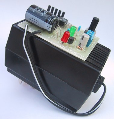
A new type of plug pack is now available.
It is a switch-mode supply and is considerably lighter, smaller and has
a high output current with very low ripple and a reliable constant
voltage. These plug packs can also be cheaper than the older transformer
design (switch-mode supplies use a very small transformer as the supply
is operating at between 50kHz to 150kHz as compared to 50-60Hz for the
older transformer design).
They are also available in 2amp to 10amp rating and are up to 95%
efficient and do not get hot.
PLUG PACK REGULATOR
If you have a plug pack that produces a voltage that
is too-high for a particular project or has has lot of hum, you can add
a circuit that will reduce the hum by a factor or 100 or more and turn
the plug pack into an adjustable output voltage.
See our project
PLUG PACK REGULATOR or
Plug Pack
Regulator
CONCLUSION
Power supplies are very important to the correct operation of any
project.
It doesn't matter if the power supply is one button-cell or a 1000 watt
supply with multi outputs; the result is the same. It must be correctly
designed.
This discussion has covered many different types of power supplies and
shown how to design, test and select the right type of supply for your
particular application.
It's very handy to know how things work and how to service them but
remember that most power supplies are connected to the mains and this
require a lot of care when the parts are exposed.
1-11-2012