TIC TAC TOE
Page 1
|
Data
and files you will need: |
This project is not to introduce Tic Tac Toe. Everyone knows
this game.
It's to introduce two features. Bi-coloured LEDs,
microcontrollers and the skill of writing an ALGORITHM.
You can use the project to learn the skills of creating the Tic Tac Toe
program or create animations on the 3x3 display.
Tic Tac Toe is one of the simplest yet most-challenging games to be invented. With just
a choice of nine locations, two players can pit their wits and very quickly
work out who is superior.
Even though the game is very simple, it has an enormous fascination. It is possible to
produce a program capable of playing the game and have a high degree of "computer win."
Although the program we have produced does not use high-level strategy, it
plays an interesting game.
The program has been kept as simple as possible to show how to produce
routines that carry out a function.
One of the sub-routines, PWin, has been written in a linear-mode to show how
long, but simple, it is. An almost identical sub-routine
is CWin. It has been written using loops and this requires extra files to keep
track of the "looping feature."
Many of the sub-routines are ALGORITHMS. This is a routine that solves a
problem. The routine looks to see if a certain condition is present and
produces an answer. This is the basis of "Computer Intelligence" or
"Artificial Intelligence." (AI). When a number of these routines are
combined and a result is obtained in a very short period of time, the computer
appears to be "clever."
There is nothing more rewarding than producing a program that delivers
"feedback" of this type. It's the programmers' high-light of the
day.
The microcontroller we have chosen is a PIC16F628. (It's an upgrade of the
PIC16F84A and with a couple of components added to the board, an 'F84 could be
used.)
This is one of the latest low-cost micro's on the market and is an
ideal starting-point for beginners to the "art of programming."
The micro is easy to use and has a re-programmable feature that allows it to be
programmed almost any number of times.
A game or toy is an ideal place to start as you know how it is played or how
it is used and it's just a matter of seeing how the
routines are created - so you can copy them or use them in other programs.
There is one other advantage of using a game. It introduces strategy. If the game is played
against the "computer" and the computer has a chance of winning, it
appears to have "intelligence."
The program for this game can be developed in two different ways -as an ALGORITHM or in
"linear-mode." An algorithm is
essentially a routine consisting of instructions that come up with a definite
answer. The program could consist of a single, extremely complex algorithmical sub-routine.
It would take hours to explain the thinking behind the structure of the
routine and beginners would be left, floundering. The solution is to produce
a
program with very simple sub-routines. And this is what we have done.
A linear-mode layout makes the micro run through the program and find a
set of instructions that applies to the particular condition. This type of layout
requires more instructions but it is much easier to follow.
Many of the programs on the web (and in books), have been developed by very clever programmers
and it may take an hour or more to work out what the program is doing!
This is not the approach we are taking. The routines we have produced are
very simple and each instruction is fully explained.
Don't be dissuaded by the length of the program. It's really
individual sub-routines that can understood if you sit down and "apply
yourself."
When the project is turned on, the screen flashes and shows the effectiveness and capability of the bi-coloured LEDs. This is called the ATTRACT MODE and is sometimes used in amusement machines to attract players. The LEDs flash from red to orange to green and then a single LED in the centre of the display gradually changes from red to green. There are 256 steps in the change. To produce this gradual effect, takes about 20 instructions and the program shows how this is done.
The routines for the ATTRACT MODE are separate from the Tic Tac Toe game and the buttons are monitored during the Attract Mode to allow the player to go to the game. When either button is pressed, the micro goes to Tic Tac Toe.
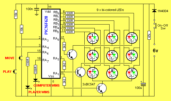
TIC TAC TOE CIRCUIT
| |
|
THE FIRST STEP
The first step is to work out how the micro will drive the display. Although the display consists of 9 LEDs, each LED contains two elements - a red and green emitter.
The output is orange when both emitting chips are driven and when either chip is driven, the output is red or green.
Other LEDs are also available with three chips inside to produce red, green and blue. When all chips are driven, the output is white light.
Bi-coloured LEDs have 3 leads. The two light-emitting parts of the LED have the cathodes connected together and this is taken to the 0v rail. In our project, we have connected the LED so that the lead to the red chip is on the left and the green is on the right.
This means the display is very similar to driving 18 separate LEDs.
This allows a scanning routine with a "run-of-three."
Since we do not have enough outputs on the micro to drive all the LEDs at the same time, we need to introduce a drive method called "multiplexing."
This involves turning on one row at a time and repeating the process at a rate that cannot be detected by the eye. The effect is to produce a display that can be fully illuminated with any LED producing any of the three colours.
As each row is turned on, six outputs from the micro take the six elements of the three LEDs to the positive rail, via current-limiting resistors.
Each line for the micro can only supply 25mA and if each LED is illuminated for 33% of the time, the average current will be about 8mA.
The brightness of a LED can be produced in two different ways. It can be constantly illuminated with a current or pulsed with a higher current for a short period of time.
In our case, the pulse of 25mA for a duty cycle of 33% is equivalent to a constant current of not 8mA but about 12mA and this is sufficient to give a very good output brightness.
Thus we will have no problem with the illumination of the display.
Once we have the scan routine worked out, we can decide on the best pins of the chip for each row of LEDs - mainly to simplify the track-work on the PC board.
We are now ready to wire a prototype and start producing routines to illuminate the LEDs.
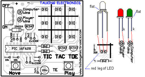
HOW TO PLAY
When the project is switched on, the ATTRACT MODE is displayed.
Push button "A" to cancel the effect and introduce an orange flashing cursor.
By pushing button A, the cursor will move across the display. Push button B to change the cursor into a red LED to indicate your move.
The computer will then make its move and show a green LED on the display.
Push button A again to bring the cursor onto the display. Push "A" again to increment the position for your next "X." The computer will then make its move.
Continue in the way to complete the game.
The "Player Wins" or "Computer Wins" LED will turn on to indicate a winner. If both LEDs turn on the game is a draw.
IMPROVING THE PROGRAM
The program has plenty of room for improvement. It has not been optimized (kept
short) nor has every strategy of the game been covered.
These are things you can investigate.
The whole object of this project is to teach the concepts of programming and
games are one of the best ways to develop impressive sub-routines. Each
sub-routine takes a number of possibilities and produces a result. The result
may be a "nil result" and the micro goes to the net sub-routine. Even so, the
generation of a "nil result" requires a functional sub-routine.
No only is the operation of each sub-routine important, but the order in which
they are placed in the program is very important.
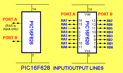
THE PIC16F628
The PIC16F628 is an 18 pin chip
with 16 in/out lines. Not all the lines are both input and output and the pinout below shows the lines with only one capability.
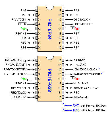
The diagram above shows the port lines for the PIC16F84A and PIC16F628.
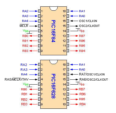
The diagram above highlights only the port-lines that are common to both the
PIC16F84A and PIC16F628.
Lines RA5, RA6 and RA7 on a PIC16F628 are not available on a PIC16F84A.
THE RULES
Everyone knows the rules of Tic Tac Toe, so we don't need to describe them here. But there is one point we should explain.
There are various levels of play to the game.
The simplest is to make a series of moves in the hope of achieving a win. The other is to "set up" the board to create a win in two directions.
In this ploy there are two approaches. One is an obvious "split" by taking opposite corners, the other is more sneaky.
It involves placing pieces on either side of your opponent and thereby creating a non-threatening situation. The next move will place a key piece to link-up the two directions and the game is won.
This can be called "levels of play" and the computer has been programmed to recognise the first two but not the third.
THE PROGRAM
A replica of the board is created in memory via Preload. It clears nine locations, from 31h to 39h. These correspond to the nine squares on the board.
The cursor uses one location before and after these so it can "hide."
The cursor starts in location 30h and moves across the board to location 3A. The program takes the cursor from location 3A and puts it in location 30h.
Each time "Move" button is pushed, the cursor moves across the display. This creates an orange flashing LED on the display.
When PLAY button is pressed, the flashing cursor is converted to red to represent the player piece and a number of sub-routines are executed to produce the best outcome for the computer.
The program consists of a Main routine that is constantly looping. It scans the display and illuminates the LEDs according to values in memory locations 31h to 39h. If a location has 01, a red LED on the display is illuminated. If the value is 04, a green LED is illuminated. If the file holds 05, both red and green are illuminated to produce ORANGE.
The cursor is "flashing orange" and to make it flash, the display is scanned a number of times (determined by the number of loops in file 22h) and then the cursor is "hidden." It is hidden by changing the value from 05 to 08. The display is looped a number of time and the cursor is placed back on the display.
The display is scanned by outputting a HIGH to LEDs on six lines of PortB. RB0, RB1, RB2, RB3, RB4 and RB5. These 6 LEDs represent the red and green elements of the top three bi-coloured LEDs. A single sinking transistor takes these LEDs to the 0v rail. The transistor is turned off and the information for the middle three bi-coloured LEDs is outputted on the 6 lines of PortB.
The middle transistor is then turned on and the elements are illuminated.
This is continued for the lower 3 LEDs.
By repeating the process very rapidly, the whole display is illuminated.
![]()