|
|
|
Page 1 |

All the circuits and projects we describe in these articles consist of very
important "building blocks" that you can add to other designs.
This time we describe the concept of touching a plate (or two
plates separated by a small gap) and turning
a circuit ON or OFF.
A TOUCH PLATE is classified as a high impedance device (or high
impedance circuit) as the effect of a finger will be detected by the
circuit connected to the plate.
To learn more about the concept of high impedance circuits, see Page 77
of our Basic Electronics course.
If only a single plate is present, the circuit will actually be picking
up "mains hum" from the finger. To prove this, take the project into an
open space such as a large park and try the circuit. It will not work.
If the plate has a signal on it (from an oscillator), the effect of your
finger will be to remove the signal (or reduce its amplitude
considerably) and a detecting circuit will be activated.
If the circuit has two plates, it will be registering the resistance of
your finger. If the circuit has 4 plates, it will use two to turn the
circuit ON and two to turn the circuit OFF.
There are a number of different types of TOUCH PLATES and different
effects can be created by the circuit.
1. Touch a set of pads and the project turns on. When the finger is
removed, the circuit turns off. The finger can touch the pads for any
length of time. We also include the feature where the circuit extends
the ON period, so the circuit stays on for a length of time after
the finger is removed. This is shown in Circuits A.
2. Touch a set of pads fairly quickly and the project turns on. Touch
the pads again for a short period of time and the circuit turns off.
This is called the "Flip-Flop" effect. If the finger is kept on the
pads, the circuit will turn on-off-on-off at a rate of about once per
second. This is shown in Circuits B.
3. Touch one set of pads to turn the circuit on and another set of pads
to turn the circuit off.
This is shown in Circuits C.
CIRCUITS A
The circuit above is the simplest Touch Switch. It is called a
"super-Alpha pair" and is actually identical to a single transistor with
a very high gain.
Putting a finger on the touch pads turns the top transistor ON and this
transistor turns on the bottom transistor. When the finger is removed,
the circuit consumes less than a microamp.
The 555 can be used to create a Touch Switch. The only problem with this is the 555 consumes about 8mA, at all times when the supply is connected. The circuit above turns on the LED when the finger is applied and pin t becomes "open circuit." This allows the 10u to charge via the 100k resistor and when pin 6 detects a HIGH, the LED turns off. The finger should be removed before this occurs. See below for an ON-OFF touch switch using a 555.
The Touch Switch circuit above is a very complex design to do a simple task. It is also a very poor design as the biasing (turn-on) for the output transistor is via a resistor and the output transistor is turned off by taking the biasing current to the 0v rail. This is a wasteful design if the circuit is to be powered by a battery.
The circuit above has a signal "sitting" on the TOUCH
PLATE via the oscillator made up of a Schmitt trigger between pins 1
and 2. The operates as a square-wave oscillator at approximately 150
kHz. The oscillator's output gets ac-coupled to R2 that sets
the drive level and hence, the sensitivity for the touch pad. Applying
negative excursions of several volts of a square-wave signal to its gate
repetitively drive N-channel JFET Q1 from conduction into
cutoff. An approximation of the square wave swinging from 0 to 12v
appears at Q1's drain. A peak detector circuit formed by D1;
R7 and C4 provides sufficient dc voltage to force
IC1B's output to a logic low.
However, if someone touches the touch pad, any added capacitance to
ground reduces the ac drive at the FET's gate, and Q1
continuously conducts. The square-wave voltage applied to D1
decreases. The voltage on C4 drops below the logic threshold,
and IC1B's output goes high. You can adjust R2 to
set sensitivity and compensate for device-to-device variations in the
FET's pinch-off voltage.
The following circuit does not work. It uses a CD 4001
The TRUTH TABLE for a NOR gate is:
| NOR GATE | |
|
INPUT |
OUTPUT |
| 0 0 | 1 |
| 1 0 | 0 |
| 0 1 | 0 |
| 1 1 | 0 |
We can see from the Truth Table that the output of a gate only changes when both inputs are LOW. For the top gate, pin 1 never goes low so this type of gate will not work.
Try a NAND gate:
The circuit above does not work. By checking the Truth Table, we see the gates are correct:
| NAND GATE | |
|
INPUT |
OUTPUT |
| 0 0 | 1 |
| 1 0 | 1 |
| 0 1 | 1 |
| 1 1 | 0 |
But the circuit does not turn off. The reason is the 4u7 is not
charge or discharged by any component in the circuit. When the circuit
is first turned on, the electrolytic is uncharged and pin 5 is
effectively connected to pin 3. If output pin is HIGH, pins 5&6 will be
HIGH and pin 4 will be LOW. This will make pin 3 HIGH. Both the Touch
Wires will be HIGH and touching them will not change the state of the
circuit.
We need a component to allow the 4u7 to charge and make pins 5&6 LOW.
The next diagram does this:

The 100k "safety resistors" have been removed as they do not
play a part in the operation of the circuit and the touch wires have
been connected to the circuit to have the greatest effect.
CIRCUITS B
The following circuits show a "flip-Flop" effect. The circuit changes
state, each time the touch pads are touched.
If a finger is kept on the touch plates in any of the toggle circuits above, the circuit will oscillate ON, OFF, ON, OFF at a low frequency. The frequency of 3 sec, 0.5 sec has been identified in the top circuit. An improvement to the Toggle Touch Switch above, to keep the charge on the 100n, is to use a second gate:
A touch switch can be made with 2 gates from a 4049UB IC, as shown in the following circuit. It has proven to be reliable at 6v and 12v. The design has the advantage that the output does not cycle if a finger is kept on the Touch Pads.
CIRCUITS C
These circuits have two touch plates.
One touch plate turns the circuit on and the other plate turns the
circuit off.
| |
| Mouse- over:
circuit work |
|
|
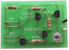
The TOUCH-PADS deliver current from the power rail to the input of the circuit, via a moist finger. The finger acts as a very high vale resistor. Note the 4M7 feedback resistor that keeps the circuit on when the finger is removed.
The circuit above is available from Talking Electronics as a kit. The kit is called TOUCH SWITCH:
TOUCH SWITCH USING A CD 4011 IC
A TOUCH SWITCH using a CD 4011 is shown in
the diagram above.
A simpler version is shown below:
When the circuit is first turned on, the two gates will
"race" and the fastest gate will create a HIGH output. It cannot be
determined if the LED will light when the circuit is first turned on. By
adding the 100p (shown in red) to the position shown on the circuit, one
input of the gate will start with a LOW and this will make pin 4 HIGH.
The top gate will have HIGH on both inputs and the output will be LOW.
This will turn on the LED. It is not know why the previous circuit used
all 4 gates of the 4011. The circuit was taken from a kit manufactured
by a non-electronics person and he did not investigate the possibility
of simplification.
Since the output of a CD 4011 is not capable of sinking or sourcing a
high current, you can buffer the output of the gate with the third gate
in the chip and wire it as an inverter.
ON-OFF TOUCH SWITCH USING A 555 IC
For those who like the rugged 555, we have included a 555
ON-OFF touch switch.
This part of the circuit board can be cut away and used as a touch pad
for the circuits in this discussion. The pads are already protected from
corrosion and form a very good design for detecting a finger.
If we take the first circuit "A" and place a finger on the
touch pad, the circuit becomes equivalent to two resistors in series.
These two resistors form a voltage divider and the voltage on the output
is in proportion to the value of the resistances. We will assume the
resistance of the finger is 1M to make the discussion simple. The 5M
resistor is not a standard value but s also used to make the discussion
easy to understand. In the diagrams below, the output of the
If we apply the same finger to circuit "B," the output voltage
will drop to 3v. This voltage may not be low enough to trigger the
circuit connected to the touch pads.
If we apply the same finger to circuit "C," the output voltage
will drop to 5.4v. This voltage will not be low enough to trigger any
circuit connected to the touch pads. Let's look at how this voltage is
created. The two resistors are 100k and 1M in series. If we convert the
1M into ten 100k resistors, each resistor will have the same voltage
across it. There are 11 x 100k resistors and this means very close to
0.6v will appear across each resistor. That is why the output voltage
will be about 5.4v when the finger touches the pad.
From this we can see the "pull up" resistor must be as high as possible
so the effect of a finger will reduce the output voltage of the pad to a
low value.
Here is a Touch Switch
circuit from a magazine:
Why use half
a chip and a FET to do the same as our 74c14 circuit above?
TOUCH PADS
A touch Pad can be obtained from many different sources. The
photos below show a touch pad obtained from a toy. Some of the very light touch
buttons consist of a small carbon block mounted in silicon rubber and
when the button is pressed, the carbon block touches the pad and reduces
the resistance between the two interleaved tracks. 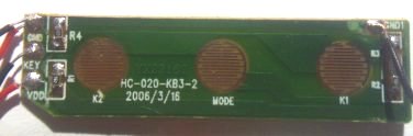
3 TOUCH PADS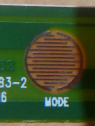
Close-up of the touch pad
The important feature of the pad is the number of interleaving fingers
as this is equivalent to a pair of lines about 12cm long and when a
finger is applied, the resistance between the lines drops to between 150k
and 850k, depending on the pressure and moisture in the finger.
HIGH IMPEDANCE CIRCUIT
We have already said a touch pad is a high impedance device (circuit),
but what does this mean and how does it work?
We are going to explain why it must be a high impedance circuit.
Below we have four different touch pad circuits. The supply
voltage does not matter, however we have shown it as 6v. The main
purpose of a touch pad is to reduce the voltage on the "output."
Generally this must be15% - 25% of rail voltage to trigger the circuit.
touch pad is 6v when nothing is touching the pad. When a finger touches
the pad, the voltage drops to 1v. Without using mathematics, we can see
the 5Meg resistor is in series with the 1Meg finger, making a total of
6Meg. This means 1v appears across each 1Meg and thus the output is 1v. 
There is one other important factor to remember.
The output of a touch pad must be connected to a high impedance input.
The diagram below shows the gates and a "super-alpha" transistor. These
all have a high impedance input. 
High Impedance Inputs
Suppose the circuit we are connecting to the touch pad has a low
impedance. It will be equivalent to placing your finger on the touch pads.
The output will go low and your finger will not be able to create a
HIGH-LOW voltage change.
The input impedance of a gate can be considered to be very high (greater
than 10M). When the "super-alpha" pair is connected to the touch switch,
the voltage on the "output" of the touch pad will not rise above 1.3v.
This is due to the base-emitter junctions of the two transistors.
The output of the super-alpha pair will be low. When a finger is placed
on the touch pads, the output of the super-alpha pair will rise.
An alternate circuit for connecting touch pads to a super-alpha pair is
shown below:
LATCH CIRCUIT
Here are two latch circuits using transistors. The first operates exactly
the same as the 4-transistor Touch Switch above. It can be used
with a touch pad. It's another "Building Block" to add to your
collection. The second circuit operates in the same way. When the
circuit is first turned on, both transistors are not conducting. As the
input voltage increases to 0.65v, the BC 547 transistor turns on and
this turns on the BC 557. The BC 557 is connected to the base of the BC
547 and it takes over from the input voltage. The two transistors turn
each other on until both are fully turned on. The supply must the turned
off to reset the circuit.
That's why you need to know how to design circuits, so you don't
over-design.
See our "Spot
The Mistake" article for more over-designed and incorrectly designed
circuits. You learn more from other people's mistakes than anything
else.
USING A TOUCH SWITCH IN A PROJECT
1.
DOORKNOB ALARM
The 74C14 (40106) is a hex Schmitt trigger IC with 6 gates
that can be used for 6 different building blocks. Even though it has a
"74" marking, it can be placed in a circuit with a voltage as high as
15v - all the other 74 series require a maximum of 5v for the supply. (More data on the 74C14 can be found in
Chip Data eBook.)
In the following circuit, the gates are used to detect the touch of a
door knob and produce an output that goes HIGH for approx 1 minute.
As the capacitance on pin 1 is decreased, the frequency of the
oscillator increases and this makes it easier for the human body to
absorb the signal. Try changing this value as well as the coupling 5p6
to 22p that connects the oscillator to the detecting gate between pins 3
and 4.
The output of the above circuit can be taken to an alarm. Open the reed switch contacts and connect the reed switch to the output of the Door-knob alarm.
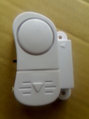
A suitable
alarm can be found in the $2.00 "Junk Shops" for about $2.00 These
consist of a piezo diaphragm and a driver circuit consisting of a
transistor and COB (Chip On Board) to produce a very loud wailing sound.
Some of the devices have an inductor to increase the voltage to about
60v to 80v to produce an output of about 90dB. The device we bought had
a transformer to drive the piezo to 80v.
The photo shows the device and magnet. The magnet holds a reed
switch closed and when the two items are parted, the reed switch opens
and sounds the alarm.
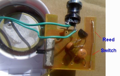
The reed switch can be seen in the photo below. It is an uncovered reed switch consisting of two soft-iron strips that overlap slightly in the centre. When a bar magnet is brought near, the two strips become magnetised with each forming a north at the top and south pole at the bottom. This means the top strip has a south pole at its bottom and the lower strip has a north pole at its top. Since unlike poles attract, the two strips will touch each other when a bar magnet is present.
When a magnetic object comes in the vicinity of a magnet, it becomes temporarily magnetised with North and South poles. This is shown in the diagram. This is how the two strips of the reed switch close and "stick together" when the magnet is near.

The magnetic field of the bar magnet causes the two
parts of the reed switch to become "magnetic."
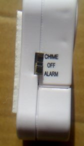
The side of the alarm showing Chime (Doorbell), Off
and Alarm. See below for a link to these sounds.
The underside of the alarm showing the COB module and the 4 pins from
the transformer that drives the piezo diaphragm. To hear the "DoorBell"
sound and "Alarm" sound, click HERE.
or here:
SOUND
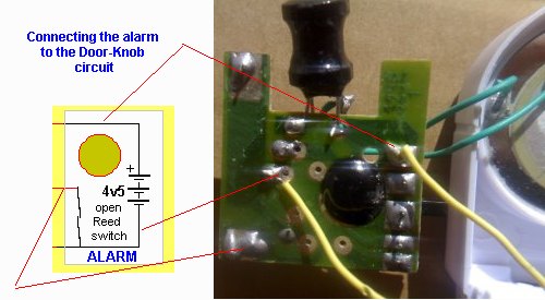
Open the reed switch so the Door-Knob circuit can operate the alarm.
2. TOUCH MOTOR CONTROL
- by L. W. Brown, Burwood,
Victoria, Australia.
The following circuit is suitable for operating a12v motor such as on a
display in a shop window. The 50mm x 50mm touch plate can be stuck to
the inside of the glass and anyone placing their finger near the touch
plate (on the outside of the window) will prevent the signal entering the charge pump section of the
circuit and keeping the 10n charged.
The circuit will take a few seconds before the 10n is discharged via the
10M and the motor will operate.
3. TOUCH-ON TOUCH-OFF
This circuit is an extension of the Door-knob Alarm presented above. It
turns on an output when the Touch-Plate is touched very briefly and
turns off the output when the plate is touched for a slightly longer
period of time.
A reader had success when the capacitor on pin 1 was reduced to 5p6 as this increased the frequency of the oscillator to approx the maximum frequency of the gate and this high frequency was readily absorbed by the body when the touch plate was touched.
TOUCH-ON TOUCH-OFF SWITCH
This article has covered more than 10 building blocks and shown how to
adapt a low-cost item in a junk shop to a circuit you have already
designed.
It has also covered the concept of a HIGH
IMPEDANCE CIRCUIT and
FEEDBACK to keep a circuit stable in either of its two
states.
Even if you think you will never need a TOUCH SWITCH in a future
project, the building blocks we have covered can be used in lots of
different circuits and if you build them, you will have a much-better
understanding of how they work.
3. TAP-ON TAP-OFF
This circuit is slightly different to all those above as it uses a piezo diaphragm to
detect the tap of a finger (it needs to be a very strong tap) to turn a
LED ON and OFF.
Four different piezo diaphragms have been tried in the circuit and all
were successful.
The resistor values can be anything from 100k to 1M and any value seems
to work equally.
The 4 diodes are just a bridge to deliver positive to the collector of
the transistor, when the input and output of the first gate changes
polarity.
The tap on the diaphragm produces a spike that turns on the transistor
and the resistance across the two points in the bridge is reduced. This
allows the bridge to put an opposite voltage on the input of the first
gate and this voltage is obtained from the 100n, which is acting like a
miniature battery. This changes the state of all three gates. The 100n
then charges to an opposite polarity, ready for the next tap.

26/11/14