|
|

The First Law of Electronics.
White LED Driver
Detecting Light With a LED
Two-wire Intercom
These pages contain ideas, tricks and helpful advice, not normally
found in any book, manual or website.
They come from the "horse's mouth" and you will find them
very helpful.
Many of the items are obvious after they have been explained, but
someone has asked for an explanation via an email and I know others will have the
same need.
FIRST LAW
The first law of electronics is: "Don't expect a circuit to work first
time."
Electronics is much-more-complex than you think and if you expect things
to work first time, you are kidding yourself. A circuit must be designed
absolutely accurately for it to work and most of the time you don't have
any idea of the value of any component. Component values come with
experience and that's why you have to look at hundreds (if not
thousands) of circuits and remember the value of every component.
One employee who worked for me, could draw the circuit of a 50 watt
stereo amplifier, with treble, bass and balance controls, from memory.
This was in the days of individual components!
When you have a passion for electronics, these things are as simple as
solving the Rubik's cube is 35 seconds.
These CIRCUIT TRICKS are in no particular order. They are added
whenever I get an email from a reader.
Before we start, I
would like to relate an incident that happened 30 years ago. An
employment agency rang me to say they had a client who was interested in
writing for a magazine.
I told them to let him ring me.
They wanted a fee of 2 weeks wages and asked me to sign a contract
before they went ahead.
I told them where to go.
Three weeks later they rang again and said they would allow the client to
ring.
He rang me and said he was a university student and could write articles
for the magazine.
I said I would try him out with a simple project.
I would send him a diagram, parts and an experimental PC board.
"Oh, I don't do any soldering" was his reply!
Now I come to an email I received the other day:
Hi, I'm Mike, I've browsed some of your projects. Most of
the transmitters you explain in detail how
an oscillator works, and show pictures and PCB of the
project. Why don't you post the transmitter output
power?
It's very lame not to show the real output power.
Example: "800m (2400ft) FM transmitter that fits on top
of a 9v battery." How can you say 800m? and not
specify the output power? you know that with 10mW you
can transmit up to 3000 meters in open air but indoors
just 5-10 metres?
Before writing an email like the one above, you must do your home-work.
Obviously the writer has never built any of the transmitters we have
designed.
We have sold over 150,000 transmitter kits and more than 15 different
designs.
The main factor that limits the range of a transmitter is the antenna.
In some of our articles we specify a 20cm antenna and say the
transmitter will only reach 10 metres, to comply with the local laws.
The transmitter will reach way beyond 10 metres, and it only requires
the reader to build the project and walk outside his house and down the
street with a radio, to see how far it will go.
But we cannot say this in the article.
The situation has now changed with the internet. No local laws apply and
we can describe everything more fully.
As a general rule of thumb, the output power is about 30% of the
consumption. If the 800 metre transmitter takes 8mA at 9v, the output
power will be about 24mW. But even this is no indication of distance as
the world record is 300microwatts output and a range of 300 miles. This
is one million miles per watt.
And we have 3 versions of the 800 metre transmitter. One uses a common
NPN transistor for the output, the second uses a high frequency
transistor and the third has a transformer matching the output to the
antenna.
The third design had a narrower output and almost twice the range. We
have tested this transmitter through houses and shops and over a slight
hill. It reached over 3km to the local shopping centre.
So, before you enter into an argument, do your homework. There are far
too many "arm-chair technicians." Never say anything unless you have
experienced it.
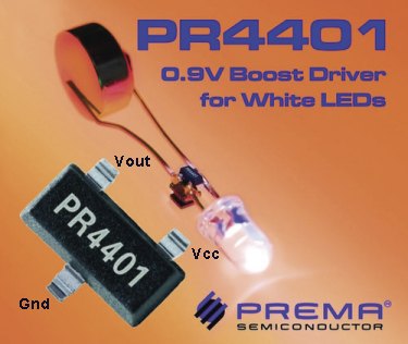
WHITE LED
DRIVER
Now I come to a
recently released surface mount chip powered by a single cell
to drive one or two white LEDs.
The characteristic voltage across a white LED is about 3.6v so you
need a step-up circuit to illuminate them.
The chip we are about to describe does this. It is called PR4401.
To learn more about driving a white LED from a 1.5v cell, see the
comprehensive article:
LED Torch
Circuits.
Here
is the advertising promo for the PR4401.
The diagram above has a number of points that need changing for better clarification and this has been done on the diagram below. The diagram above refers to a rechargeable cell, the diagram below refers to an Alkaline cell or a button cell:
Here is the promotion from Prema, with English and technical corrections by Colin Mitchell:
PREMA, PR4401
White LED Driver Requires Just One External Component
News Release from: PREMA
Semiconductor GmbH
PREMA has introduced a white LED driver designed for a variety of
applications. The core of the new driver PR4401 consists of a step-up
voltage converter to provide an output voltage of typically 3.6V for
white LEDs. The input voltage can be as low as 0.9V, thus allowing
single cell operation.
Only an inductor is required to operate up to three LEDs in series. A
regulated current of up to 23mA, depending on the inductor value,
provides a constant LED brightness independent of supply voltage.
The PR4401 offers a high efficiency of about 80% over the whole supply
voltage range from 0.9V to 2V. Thus the typical lifetime is more than 55
hours with an AA alkaline cell. An inductor value of 22µH is recommended
for a maximum battery life, while with a 10µH coil, higher currents are
achieved for maximum brightness of white LEDs.
When the supply voltage drops, the cell current will be reduced to less
than 10µA to avoid a deep discharge of the battery. The PR4401 is
available in a compact SOT23-3 package as well as a die on inked wafers.
This way, size-sensitive applications can be realised with chip-on-board
(COB) solutions. This LED driver offers a low-cost two-component
solution (plus LEDs) for small LED flashlights or small-sized torches.
Further applications for the PR4401 are LCD backlighting, for example
MP3 players operate with only one alkaline cell.
A lot of information on the
chip is contained in
PR4401.pdf (288kb) and you should read the document to get a full
understanding of how the chip can be used.
Now we come to a critical analysis of the chip.
1.
The data for the chip states it will operate for 55 hours at 33mA,
on a single AA alkaline cell, for an end-voltage of 0.9v. This gives a
consumption of 1815mAhr. The capacity of an AA alkaline cell is
2400mAhr when taken to a terminal voltage of 0.8v.
This means the chip is using only 75% of the capacity of the cell.
2.
The second point to note is the maximum input voltage for the chip. This is
1.9v.
The chip will not trigger or start properly if the supply voltage is
above 1.9v.
This is a big limitation. How many projects work from a single cell? If
the chip was designed to operate from 2 cells (3v), the terminal voltage
(meaning the end-voltage) could be as low as 1v and this would mean each
cell could be used to an end-voltage of 0.5v. This would almost double
the number of hours per cell, giving a total of more than 200 hours from
two cells.
3.
The cost of the chip is about 36 cents when buying 9,000 IC's. This is
an outlay of more than $3,200 for a single item.
The cost is too high when you consider its function. It should be less
than
8 cents. When you see the Chinese using the chip in a project, you know
the price is right. I will wait for this to happen.
4.
No supplier for the chip could be found on the internet and the other components
(inductor and surface-mount white LED) are also difficult to buy as a
single item.
I searched the internet for 3 hours and could not find a supplier or
price for the IC. I finally had to contact the manufacturer. Their
minimum order was 9,000 pieces!!!!
5.
The chip shuts down when the cell voltage reaches 0.9v. This is to
prevent deep discharge. This is ok for a rechargeable cell as some have
a "memory" and should not be fully discharged, but an alkaline cell can
be fully used-up before it is thrown away. Why not use the maximum energy from
this type of cell?
6.
Their .pdf document for the PR4401 had a number of technical
inaccuracies and I wrote to them with the corrections. Up to this point
in time, I have not received a reply!!
The photo below shows the chip and inductor soldered to a LED:

The biggest problem with designing a chip to operate on a voltage as low
as 0.9v, is driving the output transistor into saturation with a such a
low voltage. The resistor on the base must be very small as there is
only 0.2v available for the voltage drop across this resistor. To get a
collector-emitter flow of about 200mA, the base current must be about
1mA, if the transistor has a gain of 200.
When the supply voltage is increased, the base current will increase
enormously and at 1.9v, we have 1.2v available across the low-value base
resistor. The transistor will be absolutely swamped and as the document
states, the circuit may not start up if the supply voltage is greater
than 1.9v.
Yet another technical point which has not been addressed in the pdf
document is the noise produced by the chip on the power rail.
The manufacturer has stated the chip is suitable for powering a LED in
an MP3 player.
Any devices involving some sort of processor or controller or storage, are very critical when it
comes to noise on the supply. This PR4401 puts an enormous demand on the
supply as the .pdf document states the peak current of the output
transistor is 200mA.
No mention has been made about the filtering needed to compensate for
this current.
One other point you might not be aware of is the little "trick" of
batching. Prema also markets a version called PR4402 with a maximum
output of 40mA. The cost of this is 49 cents.
It is obvious the company only produces one type of IC and picks out the
ones with the highest gain and sells them for 49 cents. The others are
sold for 36 cents in lots of 9,000.
This type of "batching" has been done since the beginning of time. All
transistors are batched and even resistors were batched in the early
days as they could not produce an exact 1k resistor, for example.
By simply driving the IC with a voltage nearing 1.9v, you will get 40mA
drive out of the PR4401. It's only when the voltage drops to 1v, that
the maximum current will be les than 40mA.
These are the sort of "tricks" you have to be aware of and that's why we
have written this set of notes.
Taking these difficulties and inconveniences into consideration, I
do not recommend this chip. It's a fun chip to look at but the
limitation of single-cell operation is quite a disadvantage.
Before you look into using this chip or creating your own circuit from
individual components, there is one more alternative.
If you are designing a microcontroller project and require LEDs to be
included, it is possible to drive one or more LEDs from an output on the
microcontroller. You will need a driver transistor and if the supply is
5v, you will only need a dropper resistor. You can even produce dimming
by creating a mark-space ratio to turn the transistor on and off or
provide two transistors with different dropper resistors to get two
different levels of brightness.
For a long period of time we have been told that driving a LED with a
higher current for say 25% of the time will result in a brightness
almost equal to driving it with a lower constant current. But it will
take a lot less overall power.
This feature only works when a LED is pulsed or "flashed" for a short
period of time. The eye will see the flash and extend the duration. It's
a bit like the flash of a camera. The flash is only very brief but it
appears to last for nearly a second.
If you are using one of the new 3v microcontrollers, you will need to
add an inductor and drive the output transistor with a square wave at
about 40kHz.
This will involve creating a program in which the output is toggled and
the micro goes to the
rest of the program. The toggling will not produce an equal mark-space
ratio, as the inductor is activated for a very short period of time.
This is all part of learning how to program and the PIC LAB-1 project
has experiments on programming a PIC chip.
Alternatively you can use a charge-pump circuit. This involves driving a
capacitor (electrolytic) and about 4v5 can be obtained from a 3v supply.
This will be enough to drive some of the super-bright white LEDs as they
have a characteristic voltage of 3.2v
Most of the write-up's for this chip have been written by
people who have never seen it and never experimented with a LED
driver circuit. They have simply copied the press release from the
company.
I have experimented extensively and that's why I have presented the
points above. As an alternative, I have designed some circuits and
presented them in an article called
LED Torch
Circuits. Although they may
not be as sophisticated as the chip, they use discrete components and do
basically the same thing at a lower cost.
And they provide more flexibility with readily-available components.
They also teach you much more about the operation of a high-frequency transformer
in fly-back mode and
you can experiment further with different windings to suit different
types and numbers of LEDs.
I have tried 2 and 3 LEDs in series and found the series method
of connection is better than parallel.
The characteristic voltage across a LED changes with current and it is
very difficult to measure the "characteristic voltage drop" without placing it in a constant-current circuit,
so if you want to match LEDs for parallel operation, you need a
handful to get the few you want.
This is not required if the LEDs are placed in series.
All the circuits in the LED Torch article are suited to producing a high voltage
rather than a high current. So why connect LEDs in parallel? It is going
against the natural characteristics of the circuit.
I know "energy is energy" and the output can be converted from
"high-voltage, low current" to "low-voltage, high-current" via the LEDs,
but it seems so much more convenient to place three LEDs in series and
not have to provide any matching.
To me, the chip "falls between two stools."
It is too expensive for what it does and it is not versatile enough. The
chip should work from 3v to 0.9v and cost less than 8 cents. When this
happens, Chinese manufacturers will look at it.
To give an example, I manufacture a solar charger circuit for garden
lighting for 12 cents. It consists of two transistors, two inductors and
3 other surface-mount components on a small PC board. If I use the
PR4401, the price would increase to 44 cents! An increase of 350%. How's
that for economics!!
Before designing a project around expensive components you must make
sure you can sell it.
I made the mistake of designing a circuit around a chip that produced 4
train sounds. It was a "re-badged" chip and cost 33 cents. I eventually
found the original from China. It cost less than 12 cents!! It was
made for a talking card company that specialised in COB cards for all
sorts of occasions (the price for 100,000 was 6cents). You just never
know where the item you want will pop up.
There is one hidden factor in the pricing of all components. You can always
negotiate a bulk price for quantity. This can amount to a discount of up
to 80%. That's why you can see some US and European devices used in
Chinese manufactured goods. For instance, car phone chargers using a "buck"
regulator cost less than $2.00 for the complete item. This is $3.00 less than the
cost of the parts!! Obviously they buy components less than you could
imagine.
CHANGES
What changes would I make to the chip?
I would add an additional pin to provided the option of removing the
"turn-off" voltage of 0.9v. By connecting the pin to 0v, a
single cell would be used to the end of its life. This will
allow the chip to be used in a torch, down to the last ounce of energy
from the cell.
Changing the inductor produces a major difference in the output. The
chip needs a "trimming resistor" to change the output slightly to cater
for different types of LEDs. For instance, some white LEDs drop 3.6v,
while others drop 3.2v. A small change in the frequency of the circuit
will adjust the output current to 20mA.
UPDATE
2 years after writing the above
article, I Googled PR 4401 to see if the chip could be bought from
suppliers.
Many suppliers wanted nearly $1.00 for the chip and the postage was
$19.00 !!
Many suppliers bought a roll of 3,000 and some has 3,000 remaining or
2946 remaining.
It is obvious the sales were miniscule and I am still trying to think of
an application for this device.
You can buy a LED torch for 40 cents to $2.00 with either 1 or 3 LEDs
and a battery, so this chip does not have an immediate application.
Elektor said they handed out 120,000 chips and inductors but the
response from readers was little more than "my inductor was damaged -
will the project still work?"
There is an old, wise, saying. If you want to make money, think of an
application, before inventing something.
That's why most successes are consumables, such as soap, toilet paper
and toothpaste.
I am still thinking of an application for a PR 4401.
| Some interesting notes on
DC:DC Chips DC-DC converter chips provide a regulated DC voltage output from an unregulated input voltage. They are used in power management applications and incorporate several conversion technologies. Buck or step-down converters convert a higher DC input voltage to a lower DC output voltage of the same polarity. Using a transistor as a switch, buck converters alternately connect and disconnect the input voltage to an inductor. Boost or step-up converters convert a lower DC input voltage to a higher DC output voltage of the same polarity. Buck-boost converters can be used for either step-up or step-down conversions, and to reverse or invert voltage polarity. CUK converters use capacitive energy transfers, creating a smooth current at both sides of the converter. Charge Pump converters are suitable for voltage step-up or inversion in low power applications. Unlike most other DC-DC converter chips, charge pumps store energy in a capacitor instead of an inductor. Flyback converters are similar to buck-boost converters, but use a transformer to store energy and can provide isolation between the input and output. These devices have two distinct phases for energy storage and delivery. Forward Converters are similar to flyback converters, but use transformers in a more traditional manner, transferring energy from input to output in a single step. Important specifications for DC-DC converter chips include: regulated output voltage, input voltage, output current, quiescent current, switching frequency, efficiency, and operating temperature. Both the output regulated voltage (Volt) and the input voltage (VIN) are minimum and maximum in continuous mode (DC). The output current (IOUT) is measured under specified conditions. Measured in amperes (A) during the idling state, the quiescent current never makes it to the load. Instead, it flows from the battery to power the regulator itself. Efficiency, the ratio of output power to input power, measures the ability of DC-DC converter chips to convert input energy into output energy. For example, an efficiency of 100% means that all of the input energy is transferred to the output. DC-DC converter chips are available with a variety of features. Some devices have more than one output or channel. Others have an internal circuit to control the amount of current produced, or an error flag for monitoring outputs that drop below a nominal value. Reverse voltage protection prevents damage in applications where users can accidentally reverse battery polarity. Thermal shutdown protection turns off DC-DC converter chips when the temperature exceeds a predefined limit. Shutdown (inhibit) pins are used to disable regulator outputs. For switching applications, converters sometimes use metal-oxide silicone field-effect transistors (MOSFET) instead of diodes. Synchronous rectification means that the MOSFETs are turned on and off at the right time for efficient gating or rectification of the output. DC-DC converter chips are available in a variety of IC package types. Dual in-line packages (DIP) can be made of ceramic (CIP) or plastic (PDIP). Quad flat packages (QFPs) contain a large number of fine, flexible, gull wing shaped leads. SC-70, one of the smallest available IC packages, is well-suited for applications where space is extremely limited. Small outline (SO) packages are available with 8, 14, or 20 pins. Transistor outline (TO) packages are commonly available. TO-92 is a single in-line package used for low power devices. TO-220 is suitable for high power, medium-current, and fast-switching products. TO-263 is the surface-mount version of the TO-220 package. Other IC packages for DC-DC converter chips include shrink small outline package (SSOP), small outline integrated circuit (SOIC), small outline package (SOP) and small outline J-lead (SOJ). Here is more information: DC-DC converters accept DC input and provide regulated and/or isolated DC output in various applications including computer flash memory, telecommunications equipment, and process control systems. They are also used frequently on vehicle-mounted systems. Common converter styles include PCB mount, PC board, internal or open frame mount, rack mount, and DIN rail. Choices for nominal DC input for DC-DC converters include 12, 24, 48, 110, 280, and 360VDC. DC output is the most important parameter to consider when searching for DC-DC converters. Common outputs converted include 3.3V, 5V, 12V, 15V, 24V, and 48V. Other performance specifications to consider include output power, line regulation, load regulation, and minimum load. The wattage rating is the total nominal power output of a converter. The line regulation is the percent change in output voltage when VDC input is varied from lowest value to highest value. The load regulation is the maximum steady state amount that the output voltage changes as a result of a specified change in load. Minimum load is specified for the primary output for a converter to meet performance specifications. Common user interface options for DC-DC converters include analog front panel, digital front panel, computer interface, parallel interface, and serial interface. Application software may be included for control or monitoring. Display options include analog meter or indicators, digital readouts, and video displays. Common features for DC-DC converters include constant current supply, overvoltage protection, over-current protection, short circuit protection, and remote on and off. Constant Current (CC) designs provide an output current that stays constant with changes in load impedance. Overvoltage protection is internal circuitry that limits or shuts down the voltage output in an overvoltage condition. When present, it is most usually found on the primary output. Over-current protection is internal circuitry that limits or shuts down the current output in an over-current condition. Short circuit protection employs techniques to protect the converter in the event of a short circuit on the load may include electronic current limiting and thermal resets with automatic recovery. Some converters may have the option to turn them on or off remotely. An important environmental parameter to consider when searching for DC-DC converters is the operating temperature. Charge Pumps are circuits that generate higher voltages from low-voltage inputs by using capacitors as storage elements. Charge pumps are used in notebook computers and mobile phones. There are many types of charge pumps. Examples include charge pump phase-locked loops (CPPL), converter chips, IC converters, inductorless converters, and inductorless regulators. A charge pump phase-locked loop (CPPLL) can provide zero phase-error and an extended frequency range of operations. Converter chips can be used for both analog/digital (A/D) and digital/analog (D/A) conversions. IC converters are used in battery-operated, handheld devices. An inductorless converter can be used as a DC-DC inverter, splitter, or doubler. An inductorless regulator provides output regulation for portable applications. Specialized and proprietary charge pumps may also be available. Selecting charge pumps requires an understanding of charge pump (CP) technologies and an analysis of product specifications. Depending on the controller and circuit typology, a charge pump (CP) can double voltages, invert voltages, or generate arbitrary voltages. In some products, a charge pump circuit can provide efficiencies as high as 90 to 95%. A charge pump PLL (CPPLL) circuit can be sized to satisfy performance requirements. Important specifications for a charge pump phase-locked loop (CPPLL) include output frequency range, phase margin, reference frequency to unity-gain-bandwidth-ratio (RUR), and locking time. Regulated output voltage, input voltage, output current, quiescent current, switching frequency, efficiency, and operating temperature should be considered when selecting DC/DC converter chips. |
|
Here is a handy reference to understanding surface-mount package types: |
|
|
IC Package Type |
|
|
DIP CDIP PDIP |
Dual in-line
package (DIP) is a type of DRAM component packaging. DIPs can be
installed either in sockets or permanently soldered into holes
extending into the surface of the printed circuit board. Ceramic dual in-line package (CDIP) consists of two pieces of dry pressed ceramic surrounding a "DIP formed" lead frame. The ceramic / LF / ceramic system is held together hermetically by frit glass reflowed at temperatures between 400° - 460° centigrade. Plastic dual in-line package (PDIP) is widely used for low cost, hand-insertion applications including consumer products, automotive devices, logic, memory ICs, micro-controllers, logic and power ICs, video controllers commercial electronics and telecommunications. |
|
DPAK (TO-252) |
Discrete package
or deca-watt (DPAK). |
|
PPAK (QFN-16) |
Power packaging (PPAK). |
|
QFP |
Quad flat
packages (QFP) contain a large number of fine, flexible, gull
wing shaped leads. Lead width can be as small as 0.16 mm. Lead
pitch is 0.4 mm. QFPs provide good second-level reliability and
are used in processors, controllers, ASICs, DSPs, gate arrays,
logic, memory ICs, PC chipsets, and other applications. |
|
SC-70 |
SC-70 is one of
the smallest available IC packages. It is used in cellular
phones, PDAs, electronic games, laptops and other portable and
hand-held applications where space is extremely limited. |
|
SO-8 |
Small outline
(SO) package with 8 pins. |
|
SO-14 |
Small outline
(SO) package with 14 pins. |
|
SO-20 |
Small outline
(SO) package with 20 pins. |
|
SSOP |
Shrink small
outline package (SSOP). |
|
SOIC SOP |
Small outline
integrated circuit (SOIC). Small outline package (SOP). |
|
SOJ |
Small outline
J-lead (SOJ) is a common form of surface-mount DRAM packaging.
It is a rectangular package with J-shaped leads on the two long
sides of the device. |
|
SOT23 |
SOT23 is a
rectangular, surface mounted, small outline transistor (SOT)
package with three or more gull wing leads. SOT23 features a
very small footprint and is optimized for the highest possible
current. Because of its low cost and low profile, SOT23 is used
in home appliances, office and industrial equipment, personal
computers, printers, and communication equipment. |
|
SOT89 |
SOT89 is a
plastic, surface mounted, small outline transistor (SOT) package
with three leads and a collector pad for good heat transfer.
Unlike other packages, SOT89 lead posts are up-set and not
down-set. SOT89 is designed for medium power and high-speed
switching applications. It is also used in applications that
feature very low RDS (on), no secondary breakdown, and direct
interface to complementary metal oxide semiconductor (CMOS) and
transistor-transistor logic (TTL). |
|
TO-3 |
TO-3 is a
transistor outline (TO) package with three leads. |
|
TO-39 |
TO-39 is a
transistor outline (TO) package. |
|
TO-92 |
TO-92 is a single
in-line, transistor outline (TO) package that is often used for
low power devices. One of the oldest power packages, TO-92 is
suitable for applications in office and communication equipment. |
|
TO-220 |
TO-220 is a
transistor outline (TO) package that is suitable for high power,
medium current, and fast-switching power devices. TO-220 is used
in home appliances, office and industrial equipment, and
personal and consumer electronics. A package variant, TO-220
Full Pack, includes a fully encapsulated heat sink that does not
require extra hardware for electrical isolation. TO-220 Full
Pack has the same footprint as TO-220, provides electrical
isolation up to 5 KV, and is often used in motor drive
applications and power supplies. |
|
TO-263 |
TO-263 is the surface-mount version of the TO-220 package. TO-263 is a transistor outline (TO) package with 2, 3, 5, 6, or 7 leads. TO-263 can accommodate large dice because of its large pad design. It is suitable for high power applications due to its low resistance. Typical applications for TO-263 include home appliances and personal computers. |
| Configuration Function | ||
|
Buck |
Buck or step-down converters are used to convert a higher DC
input voltage to a lower DC output voltage of the same polarity.
Using a transistor as a switch,
buck converters alternately connect and disconnect the input
voltage to an inductor. |
|
|
Boost |
Boost or step-up converters are
used to convert a lower DC input voltage to a higher DC output
voltage of the same polarity. |
|
|
Buck-Boost |
Buck-boost converters can be
used for either step-up or step-down conversions. They can also
be used to reverse or invert voltage polarity. With buck-boost
converters, the inverting regulator converts a DC input voltage
to a DC output voltage that is opposite in polarity to the
input. The negative output voltage can be either larger or
smaller in magnitude than the input voltage. Buck-boost
converters work by storing energy in an inductor during the ON
phase and releasing it to the output during the OFF phase. |
|
|
CUK |
CUK converters use capacitive
energy transfer. The input and output inductors create a smooth
current at both sides of the converter. By contrast,
buck, boost, and buck-boost converters have at least one
side with pulsed current. The CUK
converter is named after its originator, Slobodan Cuk, of
Cal Tech University. |
|
|
Charge Pump |
Charge pump converters are used
for either voltage step-up or voltage inversion, generally in
low power applications. Unlike most other converters, charge
pumps store energy in a capacitor instead of an inductor. |
|
|
Flyback Converter |
Flyback converters are similar
to buck-boost converters, but use a transformer to store energy
and provide isolation between the input and output. With
transformers, energy storage occurs through the magnetization of
the transformer core. |
|
|
Forward Converter |
Forward converters are similar to buck-boost converters, but use a transformer to store energy and provide isolation between the input and output. The difference between flyback and forward converters is in the way in which transformers are used. Flyback converters have two distinct phases for energy storage and delivery. By contrast, forward converters use transformers in a more traditional manner, transferring energy from input to output in a single step. | |
Designing your own DC:DC converter is a very good way to learn
electronics. There are an enormous number of chips on the market to do
this type of job but most of them are very specialised and they don't teach you
the fundamentals of how the circuits work.
The DC:DC converter circuits on
LED Torch
Circuits can be made from
readily-available components and you can modify the designs to suit your
own requirements.
When designing these circuits, here are some of the things you will get
to understand:
1. The saturation of the transistor. This means the ability of the
transistor to pass the maximum amount of current - especially at low
supply voltage.
2. The ability of a coil to produce a very high voltage. This is called the
"flyback effect."
3. The principle of operation of a second winding. This is called the
"transformer effect."
4. The frequency of operation of the circuit due to the characteristics
of the transformer. This is called the
"self-oscillating" effect.
A transformer is a very complex thing, and you will learn a lot from the
LED Torch Circuits article.
DETECTING LIGHT WITH A LED
A LED is normally considered as a producer of light, but many
of them will detect light!
Although their output is very low in detection-mode, by adding a
transistor amplifier you can use them for all types of light-detecting
circuits.
Before we start, ordinary red LEDs do not work. But green LEDs, yellow
LEDs and high-bright white LEDs and red LEDs work very well.
The characteristic of a LED in this mode is very interesting.
It is a very high impedance device.
This means the resistance is very high and it produces a very low
current.
This also means it must be connected to a very high input-impedance
stage.
The output voltage of the LED is quite surprising. It will produce up to
600mV when detecting very bright illumination.
In the following circuit, the LED is fitted up-side-down so the
resistance across its terminals can be detected by the first transistor.
When the LED does not received illumination, its resistance is very high
and no current flows in the base of he first transistor. The circuit is
turned off and no current flows.
When light is detected by the LED, its resistance decreases and a very
small current flows into the base of the first transistor. The
transistor amplifies this current about 200 times and and the resistance
between collector and emitter decreases. The 330k resistor on the
collector is a current limiting resistor because the middle transistor
only needs a very small current for the circuit to oscillate. If the
current is too high, the circuit will "freeze."
The piezo diaphragm does not contain any active components and relies on
the circuit to drive it to produce the tone.
For more information on how the circuit works, see "Spot
the Mistake." Read THE OSCILLATOR CIRCUIT on the link.
It is difficult to understand how the LED works. In the diagram below,
the LED is shown in "A." The anode is connected to the base. In figure
"B" the LED is replaced by a battery and a resistor to make it easy to
understand how the circuit works. The LED produces a very low voltage
(about 200 - 600mV) and has a very high "resistance" - about 2Meg or
more. If we turn the components as shown in "C," we see the positive
voltage produced by the LED is presented to the base. The positive from
the supply flows through the 330k resistor and the voltage from the LED
adds to this voltage and finally this voltage allows a current to flow
into the base of the transistor.
As more light is presented to the LED its resistance decreases and the
voltage it produces increases. This is shown in "D."
The result is more current flows into the base of the transistor.
TWO-WIRE INTERCOM
This is a very interesting circuit using 2
transistors in each station to drive a high impedance speaker. 8R
speakers will work quite well and this is an ideal project to connect
between your work-room and the kitchen so you can be told when dinner is
ready!
If you connect the top of the 220n to the emitter of the BC557
transistor, it will produce a "call tone" in the remote speaker.
The output of the circuit is very low and the second circuit has an
extra transistors to give louder volume, especially for 8R speakers.
TWO WIRE INTERCOM
This circuit gives a much better
output