|
LED TORCH CIRCUITS |
This project illuminates a white LED and
explains how a transformer works . . .
Page 1
|
Conventional torches come in all shapes and sizes. |
|
White LEDs have different "characteristic voltages." A 1,000mcd white LED used in this project had a characteristic voltage of 3.5v and a 3,000mcd white LED had a characteristic voltage of 3.2v. Both LEDs were driven at 20mA and the 3candala LED produced a brighter, whiter light while the 1candella LED had a yellowish ring around the edge of the illumination. |
A LED torch is one of the simplest projects you can
build and it's very interesting as it uses a super-bright
white LED.
In the history of LED production, red LEDs were the first to be invented and
their output was so dim you could barely see if they were illuminated. You
needed a darkened room to see them at all.
Then came green, yellow and orange LEDs.
As time went by, the brightness improved and it came to a point
where the output would shine into the surrounding air. These were called
Super-bright LEDs.
Then came the blue LED. At first it was dull, but gradually the output increased
to a dazzling glare.
With the combination of red, green and blue, manufacturers had the potential of
producing a white LED.
This was the dream of all LED manufacturers.
Since the illumination produced by a LED comes from a crystal, it is not
possible to produce white light from a single crystal or "chip."
The only way was to combine red, green and
blue. As soon as the output of blue came up to the quality of the other colours, a white LED
was a marketable product.
The more-recent way to produce while light is to illuminate a blue LED and
surround it with a yellow phosphor coating. The yellow and blue combine to
make white light. This is called additive mixing of colours.
White LEDs are now with us and their output makes them a viable alternative to
the globe.
There is an enormous array of LED torches on the market, from $2.00
"give-aways" to $200 "rip-offs."
Although a LED torch is passable for illuminating an area, it certainly does
not have the illuminating capability of a $10 lantern, using a 6v battery.
A LED torch is more of a "fun-thing" to see how far LEDs have come in the past
few years and see what can be done with a single cell and an handful of
components.
When we first decided to produce a LED torch project, we wanted to fit the
circuit into a 2-cell torch but a white LED requires about 3.4v to
operate, and two cells produce only 3v. So we had to think of a number of ways
around the problem. That's why we have produced a number of circuits.
As you know, a LED will not operate on a voltage below its characteristic
voltage. It simply will not operate AT ALL.
This characteristic voltage depends on the type of LED and is about 1.7v for a
normal red LED, while a super-bright LED is about 3.1v - 4v.
The exact characteristic voltage varies with the colour, the
intensity of the LED, the current flowing and the way it is
manufactured. This feature cannot be altered after it is manufactured and the EXACT voltage must be
delivered, otherwise the LED will be not work or if the voltage is higher, it
will be destroyed. This is the cold, hard fact. The supply voltage must
exactly match the characteristic voltage.
This sounds a difficult thing to do, but a simple solution is to add a
resistor in series and the voltage across the LED will sit at the exact value
required by the LED, while the extra voltage will appear across the resistor. According to Ohm's Law,
a current will flow though the resistor and this will also flow
though the LED. This applies when the circuit is supplied with a DC voltage.
All we have to do is create a voltage higher than 3.4v and we can drive one of the latest
SUPER-HIGH-BRIGHT white LEDs with a single cell, using a step-up-voltage
circuit.
This will produce a series of pulses to the LED and the brightness will be
slightly higher than if a steady DC voltage is applied. These are the things
we will be covering in this project.
|
This project explains the operation of a "transformer" in flyback mode. A transformer is one of the most complex items in electronics. Even a simple hand-made "transformer" requires a lot of understanding to see how it works. This project will demystify some of the features. |
JOULE THIEF
The web is filled with circuits similar to "CIRCUIT A"
below.
Here are 3 circuits:
Although they work, the performance and efficiency can be
increased an amazing 300% by simply adding a capacitor.
AN UPDATE on how the circuit works
We will look at the Joule Thief circuit and show the improved design.
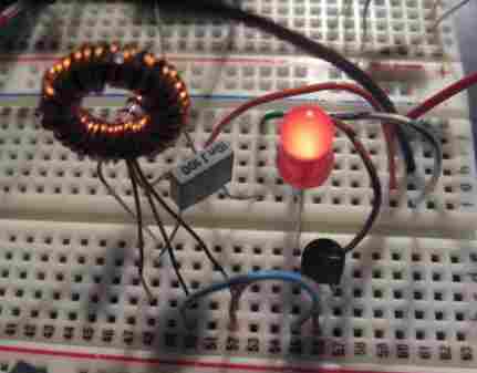
CIRCUIT A
The first circuit in this discussion is the simplest design.
It consists of a transistor, resistor and transformer, with almost any type
of LED. The circuit will drive a red LED, HIGH BRIGHT LED, or white LED.
The circuit produces high voltage pulses of about 40v p-p at a
frequency of 200kHz.
Normally you cannot supply a LED with a voltage higher than its
characteristic voltage, but if the pulses are very short, the LED will
absorb the energy and convert it to light. This is the case with this
circuit. The characteristic voltage of the LED we used was very nearly 4v and this means the voltage across
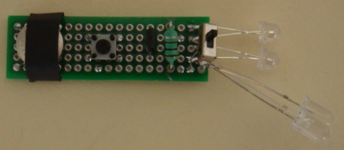
it for a very short period of time was 4v. The details of the transformer
are shown in the photo. The core was a 2.6mm diameter "slug" 6mm long and
the wire was 0.95mm diam. In fact any core could be used and the diameter of
the wire is not important. The number of turns are not important however if
the secondary winding does not have enough turns, the circuit will not
start-up. 
HOW THE CIRCUIT WORKS
The transformer is configured as a BLOCKING OSCILLATOR and the cycle starts by
the transistor turning on via the 2k7 base resistor.
This causes current to flow in the 60-turn main winding. The other winding is called
the feedback winding and is connected so that it produces a voltage to turn the
transistor ON MORE during this part of the cycle.
This winding should really be called a "feed-forward" winding as the signal
it supplies to the transistor is a positive signal to increase the operation
of the circuit. This is discussed in more detail in
Circuit Tricks.
This voltage allows a higher current to flow in the transistor and it keeps
turning on until it is saturated.
At this point the magnetic flux produced by the main winding is a maximum but it is
not expanding flux and thus it ceases to produce a voltage in the feedback
winding. This causes less current to flow into the base of the transistor and
the transistor turns off slightly.
The flux produced by the
main winding is now called
collapsing flux and it produces a voltage in the feedback winding of
opposite polarity. This causes the transistor to turn off and this action
occurs until it is
completely off.
The magnetic flux continues to collapse and cuts the turns of the main winding to produce a very high
voltage of opposite polarity.
However this voltage is prevented from rising to a high value by the presence
of the LED and thus the energy produced by the collapsing magnetic flux is
converted to light by the LED.
The circuit operates at approx 200kHz, depending on the value of the base
resistor and physical dimensions of the transformer.
The circuit draws 85mA from the 1.5v cell and the brightness of the LED was
equivalent to it being powered from a DC supply delivering 10 - 15mA.
This is an update on how the inductor/transformer works in the Joule Thief.
I have commented on a number of sites because the descriptions were
inadequate or completely incorrect.
That’s because almost no-one understands the complexity of the operation.
Just because it is two windings on a core does not mean it is simple to
describe.
It is very complex.
The circuit starts by current flowing through the resistor connected to the
base and this turns on the transistor a small amount.
I say a small amount because the main winding has a very small
resistance and it will take a lot of effort to get the transistor to deliver
a current.
However a small current flows and produces magnetic flux that cuts the turns
of the feedback winding and produces a voltage in the winding that adds to
the battery voltage.
This extra voltage allows a higher current to enter the base and the
transistor turns ON more. This is called POSITIVE FEEDBACK and it
continues very quickly to turn the transistor ON to its maximum.
This is called its SATURATION STATE and cannot be turned on any more.
Up to this point in time the transistor has been turning on more and more
and producing an EXPANDING FLUX to produce a voltage and current in
the feedback winding.
But as soon as the transistor becomes saturated, the flux is a maximum but
it is not expanding and immediately the feedback winding stops producing a
voltage.
The transistor ceases to be turned ON and the current stops flowing in the
main winding.
The transistor effectively disappears from the circuit and only the LED is
connected to the winding.
However the winding has put magnetic flux into the core of the toroid and
the winding is wound around this core.
The electromagnetic lines of force (called electro-magnetism) cannot be
maintained and we say they start to collapse. In the process of collapsing
their strength gets less and less (weaker) and this puts a voltage into the
winding that is in the opposite direction to before.
This voltage will add to the voltage of the battery and since the battery is
1v, it only needs another 2.2v and the LED illuminates.
The collapsing flux now increases the current in the winding to make the LED
flash very brightly. The voltage cannot increase because it is being limited
by the LED and so the other component of “electro-magnetic induction” occurs
(production of current).
This is proven by the fact that the brightness of the LED depends entirely
on current-flow.
At the same time the feedback winding produces a voltage in the opposite
direction that can be 10v to 20v or more. . . . . . I don’t know. . . . .
but it turns off the transistor and this continues until the winding
produces almost no voltage and the battery voltage can deliver 0.65v to the
base to start the next cycle.
A point to note: when the voltage on the base is less than 0.5v, the base
will appear as a very high impedance and this will be the case even when the
base is minus 5v to minus 7v.
If a 10n to 20n capacitor is placed between the base resistor and 0v rail,
it will get charged in the negative direction and as soon as the flux
reduces, the capacitor will hold its charge until the flux is almost zero
and then it will begin to discharge. This will increase the period of time
when the LED is not illuminated but not affect the appearance of brightness
(due to our eyes Persistence Of Vision). However the current taken by the
circuit will decrease to 30% of the previous current and make the circuit
300% more efficient.
When the magnetism produced by the circuit STOPS, the magnetic lines of
force in the core start to collapse very quickly. This effect produces a
very high voltage in all windings of the opposite direction and if a winding
is connected to a load, current will be produced in the winding and this
will act against the collapsing flux to slow-down its effect and speed.
This is a minor effect. And we have basically neglected it.
Before we go any further, there are a number of interesting circuits on the web.
Here is a circuit from one of the major chip manufacturers:
Apart from the circuit being enormously complex and expensive, 62mA is too high
for many white LEDs. The maximum current must be kept to 20 - 25mA.
The first "poor design" got me thinking. Maybe the signal at the transformer
end of the 220R needs to be stabilised to improve the performance of the
circuit. I tried a transistor and it did not work.
The brightness of the LED did not alter but the current changed from 85mA to
28mA.
Here is a photo of Circuit B constructed by a reader. He used a toroid (a
circular magnetic circuit - or ring) and this has lower losses because the
magnetic flux does not emerge (come out of) the end of the core. The
magnetic flux keeps circulating. However if the flux is not very high, it
does not saturate the core and there are no losses and the slug performs
almost the same as a toroid.
The following two circuits need explaining. The first circuit is identical
to our "Circuit A" except the design engineer did not do his homework. He
only added 8 turns to the 100uH inductor and found the circuit did not
start-up. His solution was to add another transistor and tie the base to the
collector. What a waste of a transistor!
The second circuit is a very inefficient design. The second transistor is
being turned on via a 1k resistor on the collector of the first transistor and when this "turn-on" current is not
required, it is being shunted to "deck."
Our circuit uses the "oomph" of the secondary winding to saturate the
transistor and this produces the highest efficiency.
But I actually thought of placing a small capacitor at the join and taking
the other end to the 0v rail. This will allow rail voltage to enter the
feedback winding of the transformer but prevent the signal generated by the
winding being lost through the 2k7 resistor.
The following circuit is the result:
The circuit instantly became 300% more efficient.
I could not believe it.
The capacitor was holding a charge and and the circuit took longer to remove
the charge and start the next cycle. This means the LED was illuminated for
less time per cycle but it still produced the same brightness for the flash.
If the brightness of the LED is equal to a DC voltage of 4v and a current of
10mA, the circuit we have produced is slightly more efficient than
delivering a DC voltage to the LED, even though
there are some losses in the transformer and transistor.
This proves the fact that LEDs driven with a pulse, are more efficient than
being driven by a DC supply.
You can clearly see the number of turns on the
toroid.
The circuit is not very efficient because it does
not have a capacitor to improve the efficiency.
MORE ON THE INDUCTOR - answers to your
questions
We all know that a
transformer can increase the output current and it can be greater than the
input current, providing the wattage of the output is not greater than the
input wattage.
This means a transformer works on WATTAGE.
In other words, a high input voltage at low current can be converted to a
low voltage with high current.
We are going to talk about the joule thief circuit with an inductor.
We are only concerned with the primary winding and how it converts magnetic
flux into high current.
We know it delivers a high current cause the LED flashes very bright and
this can only happen when a high current flows.
But the circuit takes less than one tenth of the delivered current.
The answer is simple.
The circuit takes a small current for a relatively long period of time and
it delivers current to the LED for a very short period of time and you eyes
have a feature called Persistence Of Vision which makes it appear the LED is
illuminated almost constantly.
It actually flashes for less than a tenth of the time.
But how is the high current produced?
When the circuit turns off and the magnetic flux collapses, the only things
that is connected to the inductor is the LED. The transistor is “out of
circuit” and the feedback winding has no load.
The LED is connected to the winding via the battery but the battery plays no
part in this part of the cycle as it has a very low voltage.
The LED is connected directly across the winding and as the magnetic flux
collapses, the LED turns ON at say 3.2 volts. At this point in the cycle
current starts to flow and although the winding is capable of producing 30v
when no load is present, the voltage does not rise about 3.2v in this case.
The core still has a lot of magnetic flux and it has a lot of strength and
it will produce a very high current.
But it can only deliver this current for a very short period of time and the
LED flashes very bright for much less than a millisecond. Your eyes see this
and retains the image on your retina for a long period of time. The next
flash occurs before you lose the image.
That’s why the LED appears to be constantly lit.
The circuit takes a long time to produce the magnetic flux and a very short
time to deliver it. That’s how the multiplied currently is produced.
But that’s not all.
The high current in the winding produces a magnetic flux that opposes the
collapsing flux and slows down the collapsing flux to produce an effect that
takes much longer to occur. This is only microseconds but it adds to the
time the LED is illuminated and also reduces its brightness.
A coil, inductor and transformer is a very complex component and very little
information has been provided in any text book or video.
The fact that the cycle stops when the transistor is saturated, is
overlooked in most discussions.
And the voltage reverses when the magnetic field collapses is another
important part of the cycle.
The fact that the voltage is limited to 3.2v on the main winding does not
limit the voltage on the feedback winding.
This type of inductor, with a ferrite core will produce about 1v to 2v for
each turn in collapsing mode.
This means the feedback winding will produce 20v or more to the base via the
1k resistor.
This voltage will be a negative voltage and turn the transistor off. The
base will accept a negative voltage as low as 5v to 7v and then the
transistor becomes a low impedance path and the current will flow through
the 1k resistor.
This will remove some of the collapsing magnetic flux.
It is important not to saturate the core of the toroid as the current
passing into the main winding will simply be lost in heating the core and
will not be recovered in the next part of the cycle.
You can use all sorts of metals for the core of the inductor, provided it
does not get saturated.
Nails, steel bolts, brass bolts can all be tried with amazing success.
That’s because the circuit is a very low energy arrangement.
You can even use AIR COILS, as air has a very small capability of holding a
magnetic field and by moving the two coils near each other you can get
different effects. In general you will need a lot more turns.
The original 30 turns + 30 turns coil is
shown on the right. The circuit took 20mA to illuminate two LEDs.
The circuit can be made small by using a
ferrite slug 2.6mm diam x 7.6mm long.
2-TRANSISTOR CIRCUITS
In the circuit above, the base current is constant and will be very small
through a 10k resistor.
The circuit turns ON via the 220k resistor and the voltage on the collector
of the NPN transistor drops to nearly 0v. This action causes current to flow
through the inductor and at the same time the 1n capacitor is brought
towards the 0v rail and this turns ON the first transistor slightly harder.
This action continues until the driver transistor cannot be turned on any
more.
This circuit is designed for mass production as the choke is a standard
33uH.
With this we turn to a surface-mount chip that has been designed to carry
out the exact same task as circuit B. The chip is called PR4401. The
following is the promotion advert for the chip:
I could not find any sales literature on the internet, but the manufacturer
requires 9,000 pieces to be bought at a cost of 36 cents per piece. This
comes to $3,240 if you want to incorporate it into your project.
LED TORCH - JOULE THIEF - INDUCTOR TESTER
An equivalent IC (chip) has come on the market for 10 cents and it is a
better chip.
Using 220uH, the circuit takes 13mA an illuminates 2 white LEDs very
brightly.
Here is the prototype:
The kit comes with a PCB, all parts: QX5252 Chip, tactile switch, 1.5v
button cell, tinned copper wire for cell and heatshrink for cell-cover,
100uH inductor, very fine wire and 1M to make your own 100uH, 2 machine pins
and length of fine solder, but only 2 LEDs and not the change-over switch.
The prototype has been built on Matrix Board and shows the change-over
switch used to test different LEDs. You will get the Printed Circuit
Board in the kit that has been generated from the layout. This is the
easiest and simplest way to make a PCB and avoid any mistakes.
Here is the waveform:
What is happening?
When you build circuit "B," you will realise the specifications given in the
.pdf for the chip, could be
improved. We have achieved a supply current of 18mA for an equivalent
brightness of 10mA. The chip requires 25mA. So, all the technology in the
world has not surpassed a hand-made circuit.
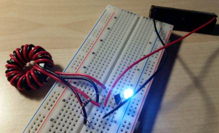
BIKE FLASHER - Amazing!
This bike flasher uses a single transistor to flash two white LEDs from a
single cell. And it has no core for the transformer - just AIR!
All Joule Thief circuits you have seen, use a ferrite rod or toroid
(doughnut) core and the turns are wound on the ferrite material. But this
circuit proves the collapsing magnetic flux produces an increased voltage,
even when the core is AIR. The fact is this: When a magnetic filed collapses
quickly, it produces a higher voltage in the opposite direction and in this
case the magnetic field surrounding the coil is sufficient to produce the
energy we need.
Wind 30 turns on 10mm (1/2" dia) pen or screwdriver and then another 30
turns on top. Build the first circuit and connect the wires. You can use 1
or two LEDs. If the circuit does not work, swap the wires going to the base.
Now add the 10u electrolytic and 100k resistor (remove the 1k5). The circuit
will now flash. You must use 2 LEDs for the flashing circuit. 
BIKE FLASHER - AMAZING!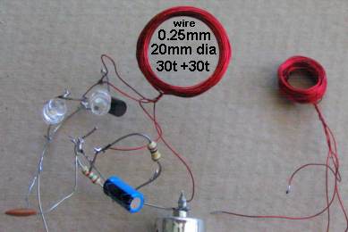
THE IMPROVED BIKE FLASHER CIRCUIT
The secret to getting the maximum energy from the coil (to flash the
LEDs) is the maximum amount of air in the centre of the coil. Air cannot
transfer a high magnetic flux so we provide a large area (volume) of low
flux to provide the energy. The larger (20mm) coil reduced the current
from 20mA to 11mA for the same brightness. This could be improved
further but the coil gets too big. The two 30-turn windings must be kept
together because the flux from the main winding must cut the feedback
winding to turn ON the transistor HARD.
When the transistor starts to turn ON via the 100k, it creates magnetic
flux in the main winding that cuts the feedback winding and a positive
voltage comes out the end connected to the base and a negative voltage
comes out the end connected to the 100k and 10u. This turns the
transistor ON more and it continues to turn ON until fully turned ON. At
this point the magnetic flux is not expanding and the voltage does not
appear in the feedback winding.
During this time the 10u has charged and the voltage on the negative
lead has dropped to a lower voltage than before. This effectively turns
off the transistor and the current in the main winding ceases abruptly.
The magnetic flux collapses and produces a voltage in the opposite
direction that is higher than the supply and this is why the two LEDs
illuminate. This also puts a voltage through the feedback winding that
keeps the transistor OFF. When the magnetic flux has collapsed, the
voltage on the negative lead of the 10u is so low that the transistor
does not turn . The 100k discharges the 10u and the voltage on the
base rises to start the next cycle.
You can see the 100k and 1k5 resistors and all the other parts in a
"birds nest" to allow easy experimenting.
This is the first circuit you should build to flash a white LED from a
single cell.
It covers many features and shows how the efficiency of a LED increases
when it is pulsed very briefly with a high current.
The two coils form a TRANSFORMER and show how a collapsing magnetic
filed produces a high voltage (we use 6v of this high voltage).
The 10u and 100k form a delay circuit to produce the flashing effect.
You can now go to all the other Joule Thief circuits and see how they
"missed the boat" by not experimenting fully to simply their circuits.
That's why a "birds nest" arrangement is essential to encourage
experimenting.
Note: Changing the turns to 40t for the main winding and 20t
for the feedback (keeping the turns
tightly wound together by winding wire around them) reduced the current
to 8-9mA.
The inductance of this transformer is quite critical and the voltage
across the LEDs must be over 6v for the circuit to work. It will not
work with one or two LEDs.
The circuits we have presented above use a
single transistor and a transformer to provide feedback. This feedback is a
form of REGENERATION to turn the transistor on HARDER and HARDER to
produce the maximum efficiency.
An oscillator can be produced with two transistors and an inductor, but
there are some design-features that need to be applied to produce an
efficient circuit.
The first circuit is a POOR DESIGN.
Base-current is effectively wasted current or "wasted energy" and
should be kept
to a minimum.
The circuit consumes 10mA and the LED will see less
than 4mA.
By reducing the 10k base bias resistor to 470R the circuit-current increases
to 25mA but the LED is still not at full brightness.
Secondly, the base-current is shorted to the 0v rail via the first
transistor and is completely wasted during part of the cycle.
But the main problem with the circuit is the fact that the driver transistor
is not driven into full conduction at any part of the cycle and the circuit
has very little efficiency.
To solve this problem, the two transistors are connects so the "turning-ON"
is provided by a transistor and it effectively reduces in resistance to a
small value to turn ON the driver transistor.
Theoretically a current-limiting resistor should be added in the base of the
driver transistor (about 47R) but this made no difference to the current
taken by the circuit. 
The 1n charges a little more and the current through the base lead reduces
slightly. This action turns OFF the first transistor slightly and the driver
transistor is turned OFF a slight amount.
The voltage on the 1n rises and very soon both transistors are fully turned
OFF.
The magnetic flux in the core of the 1mH inductor collapses and produces a
voltage in the opposite direction.
This voltage is added to the 1.5v rail voltage and the final voltage is high
enough to illuminate the white LED.
This keeps both transistors OFF and when all the magnetic flux has been
converted to energy to illuminate the LED, the voltage on the collector
drops. This lowers the top plate of the capacitor and since the capacitor is
slightly charged, the bottom plate drops to a voltage less than rail
voltage. This action turns ON the first transistor to start the next cycle.
It can be made by winding 50 turns of 0.1mm enamelled wire on a 1.6mm diam
ferrite slug.

I have described the pro's and con's of this chip in another article "Circuit
Tricks" and you should read it and work out what
they really mean.
Kit of components $3.00 plus $4.00 postage
Here is the circuit for QX5252F:
Using 100uH the circuit takes 30mA and the LEDs are really the same
brightness.
Using 33uH the circuit takes 80mA and the LEDs are just about the same
brightness.
Obviously the 220uH creates the most efficient circuit.
Email
Colin Mitchell for details on buying
the kit.
The inductor has been fitted via machine pins and it can be removed and
different inductors fitted to see the results. A machine pin is hollow and
allows to poke the ends of a conductor into the pin and it will make
contact.
The current taken by the circuit changes according to the inductance and
this will enable you to compare inductors and even find the value of an
unknown inductor.
You need to use one, two or three known inductors and make a table of the
inductance and current taken by the circuit.
The current may or may not be linear but we measured inductors from 33uH
1,000uH and recorded currents from 80mA to 2.5mA.
This enabled us to measure unmarked coils.
One more feature of this project is to wind your own inductor and see if
it is effective as the 100uH supplied in the kit.
The kit comes with fine wire and a 1M resistor.
Wind 250 turns on the resistor very carefully and as you come to the end of
the winding, you can criss-cross the wire over the other turns to keep them in
place.
Leave at least 4cm of wire at the beginning and end.
Now heat the wire very close to the body of the resistor with a hot clean soldering iron that has been fully
tinned. The wire will get tinned very close to where it comes from the
winding. Now wind 5 turns around the wire coming from the resistor and
solder it in place. Break off the wire.
Do the same with the other end.
Fit your home-made inductor and the LED should be as bright as the 100uH.
Measure the current across the switch. It should be about 32mA.
The voltage is being converted from 1.5v to 3.5v and each LED will get
slightly less than 6mA by the time you take the efficiency of the circuit
into account.
The first part of the cycle shows the inductor being pulled down to the 0v
rail.
This means the 1.5v for the battery is directly across the inductor and
current starts to flow in the winding.
This produces magnetic flux (called EXPANDING FLUX) that cuts all the turns and produces a voltage
in the turns that is opposite to the incoming voltage.
This means the effective voltage entering the inductor is very small and
thus a small current flows. However enough current flows and enough time is
allowed so the inductor produces magnetic flux.
This is shown in diagrams A and B.
The circuit then immediately turns OFF and the magnetic flux collapses very
quickly.
This is shown in diagram C. This voltage is actually in the opposite
direction to the original voltage and this is one of the most important
things to understand.
The voltage produced by the inductor will be very high (possibly 10v or
more) (and is added to the voltage of the battery. But as soon as the voltage reaches 3.2v, the white LED starts to turn
ON and produce illumination.
The magnetic flux keeps collapsing and supplying energy to the LED for about 2uS
and when the voltage falls to less than 3v, the LED turns OFF.
The QX5252 IC turns ON again and pulls the inductor to the 0v rail to start
the next cycle. The IC operates at about 130kHz and if the inductor has
not lost all its magnetic flux, it will add to the flux on the next cycle.
You can see the inductor only has to produce about 1.7v as the voltage is
"produced" on top of the 1.5v from the battery. The circuit will work down
to about 0.9v
Understanding and interpreting a waveform is very important because the LED
is only turned ON for a very small portion of the time but it is turned ON
very brightly.
Our eyes detect this brightness and hold this brightness while the LED is
completely turned OFF during the rest of the cycle. This effect is called
PERSISTENCE OF VISION.
This is why a very small current will produce high brightness and create a
highly effective circuit.
That's how the circuit got its name: Joule Thief. It appears to get
energy from nowhere. But we know a LED can operate in pulse-mode and product
a very high brightness while consuming a small OVERALL current.
This project will teach you 3 things:
The number of turns to create 100uH inductor, testing different inductors,
testing different LEDs and determining the value of inductance by measuring
the current.
oooooooooooooooooo000000000000000000000000000oooooooooooooooooo
The advantage of our design is the ready availability of components and you
can change them to suit your own application.
If you want to increase the brightness, the 2k7 can be reduced to 1k5.
If you want to drive 2 LEDs, they can be added in series:
Adding a 100u across the battery will increase the current by 4mA and the
brightness will increase slightly.
When 2 LEDs are placed in series, the current drops from 28mA to 23mA and
the brightness from each LED is slightly less. This circuit is operating at
about the maximum capability of the transformer. The actual limiting factor
is the size of the "core." It can only "hold" a certain amount of magnetic
flux and return it to the windings during the collapsing part of the cycle.
A larger core will allow three or more LEDs to be illuminated.
The "high efficiency" of this circuit is due to the "pulsing of the LED." When a
LED is pulsed with a high current for a short period of time, the brightness
is equivalent to a lower, steady, current. That's why a current of 23mA from
the battery will illuminate 2 LEDs with an equivalent brightness of about
8mA of steady current. It is very difficult to compare the brightness of one
LED against another and
these results are the best you can make by visual inspection. We are
not driving the LEDs to their maximum but the output is very impressive.
THE TRANSFORMER
The secret of this circuit is the transformer.
We normally think of a transformer as a device with an input and output, with the
voltage on the input and output being connected by a term called
"turns ratio."
If the output has more turns than the input, the output voltage will be higher.
This is called a step-up transformer. If the output has less turns than the
input, the output voltage will be lower.
This applies to "normal" transformers where the voltage is rising and falling
at a regular rate, commonly called a "sinewave."
But the transformer in this circuit is different.
The voltage applied to it is not rising and falling smoothly, and thus it does
not work in normal "transformer mode."
The voltage is being applied and then turned off. When the voltage is
applied, the primary winding (the 60 turn winding) produces magnetic flux.
When the voltage is turned off, the magnetic flux collapses and produces a
VERY HIGH voltage (in the REVERSE DIRECTION), in all the windings.
Our transformer is really a coil in flyback mode with a feedback
winding.
The feedback winding delivers a voltage to the transistor to turn it on HARDER.
If the winding is connected around the wrong way, the circuit will not work.
The other important factor about the transformer is the core material. There
are many different types of ferrite. Ferrite is a type of iron which is
powdered very finely so that the magnetic lines that pass through the
particles do not create eddy-currents. These eddy currents absorb the
magnetic flux. The material we have used is F29 and this is suitable for
high frequency applications.
The circuit also employs a term called RE-GENERATION. This is the effect
where a circuit is turned on slightly by a component (the 2k7 base resistor
in this example) and then the transistor
turns itself on more and more until it is fully turned on. The feedback winding is configured so that the
voltage it produces (actually the current it produces) is fed into the base
to turn the transistor on.
Thus the feedback winding is very clever. It produces energy and is delivered in a particular direction
- in other words it can be a positive or negative energy. In this case
it produces positive energy, to turn the transistor on harder.
This is called POSITIVE FEEDBACK as it turns the transistor
ON during the active part of the cycle.
Now we come to the MAIN, PRIMARY or FLYBACK winding.
This winding produces a high voltage during part of the cycle (the FLYBACK
part of the cycle) and this is passed to the LED.
If the LED is removed, the transformer produces a high voltage with a low
current, but when the LED is inserted, an amazing thing happens. The energy
from the transformer is converted to a lower voltage with a higher current.
What actually happens is the LED absorbs the energy and turns it to light as
soon as the voltage rises to 3.6v.
We could achieve the achieve the same low-voltage, high current requirement, with less
turns, but the number of turns has actually been determined so the core does
not saturate.
The voltage for the LED is produced when the transistor is
switched off and the magnetic flux in the ferrite core collapses.
The speed of the collapse produces a very high voltage in the
OPPOSITE DIRECTION and that's why a positive voltage emerges from the end
connected to the LED. These two facts are important to remember.
The other important fact is called "transformer action." This is the action of
magnetic flux.
When a voltage is applied to a winding of a transformer or a coil of wire, a
current will flow and this will produce magnetic flux. If another winding is
present, the magnetic flux will cut the turns of this extra coil and produce a
voltage in it.
However, there is a very important point to remember. The magnetic flux can
be: EXPANDING, STATIONARY or CONTRACTING.
When the magnetic flux is expanding, a voltage will appear in the second
winding mentioned above.
When the magnetic flux is stationary, NO VOLTAGE will appear in the second
winding.
When the magnetic flux is contracting a voltage will appear in the second winding with
REVERSE POLARITY.
The size (the amplitude or "value") of the reverse voltage will depend on the
speed of the collapsing magnetic flux. If the flux collapses quickly, the
amplitude will be very high.
That's how the transistor turns itself on and on until it is fully turned
on. At this point the current flowing through the circuit is a maximum but
the flux is not expanding so the base of the transistor does not see the
high "turn-on" energy and thus the transistor suddenly turns off.
The magnetic flux collapses and the transistor sees a reverse voltage on the
base to keep it turned off until the flux is fully collapsed. The current
through the 2k7 enters the base to start the cycle again.
From this you will be able to see how the
transistor and transformer work.
THE FLASHER
Now we come to the problem of flashing a white LED, using a 1.5v supply.
The following circuit performs this task:
The oscillator charges the 100u via the 1N 4148 diode and when the voltage
reaches about 10v, the BC 547 transistors "zeners" (breaks down) and conducts.
Energy
in the 100u is then dumped into the LED to make it illuminate. This causes
the voltage across the 100u to drop and the transistor comes out of
conduction. The oscillator then continues to charge the 100u to repeat the cycle.
The zener voltage of the transistor is not 10v as approx 4v is dropped
across the LED. This conforms with an article on the web that said the
emitter-collector junction is equal to a 6v2 zener.
The 330R charging resistor produces a fast flash and the 1k produces a slow
flash.
The current for the circuit is approx 22mA and any type of LED can be fitted.
Measuring the current-consumption of a circuit is a very difficult thing to
do. When you insert a a meter into the positive line (or negative
line) of a circuit, you introduce extra resistance and the operation of the
circuit will alter. You may think the low resistance of an ammeter will not
affect the performance, but quite often the "ammeter " is really a "milli-amp
meter" and the "shunt resistance" on the 200mA scale can be 4 - 7 ohms. This
is quite considerable when a circuit is operating on 1.5v and drawing 30mA.
This can be a loss of 100mV to 200mV and the current taken by the circuit
will alter considerably.
That's why the best approach is to place a 1 ohm resistor in line with the
positive of the battery and measure the millivolt drop across the resistor.
Each millivolt drop will correspond to 1mA flow and this will change the
circuit conditions as little as possible. The following circuit shows how
this is done:
A 100u electrolytic across the circuit will reduce the impedance of the supply and keep the circuit working as normal as possible.
As a point to note: The White LED Flasher circuit did not start-up on a flat
AAA cell.
Solution: take two flat cells and connect them in series and see how long
the LED will flash. You will be very surprised. The circuit will draw about
30mA and the LED will flash very quickly.
The circuit will continue to work on two very flat cells until the flash
rate drops to one flash per second.
This type of circuit puts a very heavy "strain" or "noise" on the power
supply. In other words it puts a heavy demand on the battery for a short
period of time.
This is not a problem if the only item connected to the battery is the
flasher circuit. But if the battery is also driving a circuit such as an mp3
player or microcontroller, the high-frequency noise may upset the operation
of the electronics.
THE OSCILLATOR TRANSISTOR
The oscillator transistor needs to sink a very high current for a very short
period of time (as mentioned above) and thus it must be a "high-current"
type. A "high-current" type improves the efficiency of the circuit. If the
transistor cannot sink the transformer to the 0v rail, it effectively
becomes a "resistance" in the network. Suppose the supply is 1500mV (1.5v
, 1v5) and the transistor can sink to 500mV, 30% of the voltage is dropped
across the transistor and thus the circuit is using only 66% of the incoming
energy. If the transistor can only sink to 0.75v, the circuit is using 50%
of the incoming energy.
Some transistors can sink to 0.3v and thus the circuit is more efficient.
STABILITY
Now we come to the stability of the circuit. The circuit is very unstable
and very unreliable. Touching the components with a finger changes the
frequency of the flash-rate and connecting CRO to the collector of the
oscillator transistor inhibits the flashing. The oscillator keeps working
but the zener transistor fails to operate.
This circuit is totally unsuitable for a commercial design and it reminds me
of some of the original transistor flasher circuits. They required precise
values of resistance and did not work when the supply voltage dropped.
Fortunately someone came up with the flip-flop flasher and changed
everything. It is totally reliable and operates under all sorts of
conditions.
Now we come to the design of a higher output circuit, to satisfy those who
want to use a larger cell and drive 2 or 3 LEDs to maximum brightness.
HIGHER OUTPUT
To drive more LEDs, a higher output is needed. We have already mentioned,
the limiting factor with the circuits above is the transformer. To achieve a
higher output, the size needs to be increased. This is quite easily done by
getting a larger core. It is the core that determines the amount of flux
that can be stored. When turns are wound on a core, the result is called an
inductor and when a second winding is added, the result is called a
transformer.
Most of the inductors and transformers we use in the circuits in this
article have an open magnetic circuit. This means the flux escapes out one
end of the core and in general the result is not very efficient. But it has
proved to be satisfactory.
An improved core is called a "pot core" and consists of two halves as shown
in the diagram below:
The magnetic lines go around the
"magnetic circuit" as shown in the diagram above and pass through an air
gap. The air gap is to compensate for the DC across the coil (transformer).
If the air gap is closed up, the inductor will saturate before the circuit
is fully conducting and this may make the inductor less effective. All this
theory is very complex and you really have to try the component to see the
effect.
The bobbin is re-wound with 35 turns of 0.5mm wire for the primary and 20
turns for the feedback winding. The two pins connect to the primary and the
20 turn-winding is wound on top, with flying leads. The gauge of the wire is
chosen so that the windings completely fill the bobbin. The feedback winding
can be a thinner gauge, without any detriment to the operation of the
circuit. By the appearance, you could expect up to 5-10 times more output
from the bobbin.
Our circuits use a simple "in line" inductor as shown above or a "bobbin" as
shown below in the third item. The photo below shows the "slug" transformer used in circuits A, B,
and C and the "bobbin" transformer used in circuit D. The size of each
transformer gives some idea of the relative output. The centre inductor is a 10mH
choke. This is unwound to get the bobbin for the transformer. 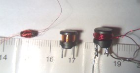
But with a higher output, you need to provide some form of energy-limiting
circuit to prevent damaging the LED.
The following circuit provides current limiting so that the LED will produce
maximum brightness for the voltage range 1.5v to 0.9v.
This gives a choice to suit a variety of torches. The smallest
penlight torch will only have enough room to drive a single LED while the larger "C" and
"D" cell torches will drive two or three LEDs.
There are some slight differences between each of the circuits and you need to
read the article if you want to deviate from any of the layouts we have given.
For instance, the 2SC 3279 transistor is capable of sinking 2 amps and this
makes it a better driver for circuit-2 but its collector-emitter voltage is
only 10v and it may zener in circuit 3, where the voltage is very near this
value.
Circuit-1 drives one LED from a single cell
Circuit-2 drives two LEDs from
a single cell
CURRENT REGULATION
The circuit includes a feature called "current regulation." You can
also call the feature "voltage regulation" as both have the same effect of
controlling the brightness of the LED.
It can also be called a "constant brightness" arrangement.
It's a feedback arrangement consisting of a BC 547 connected to the base of the main transistor.
When the voltage across the "detector resistor" rises above 0.7v, the BC 547
turns ON and prevents the main transistor operating.
This allows the LED to produce a constant brightness over a wide supply voltage.
The circuit will theoretically work to 0.8v.
Do not remove the current regulating transistor as the circuit will over-drive
the LED when the supply is 1.5v. The excess current will instantly destroy the
LEDs.
The actual operation of the circuit can be explained in a little more detail.
When the circuit is turned on, the oscillator transistor produces a high
voltage from the inductor and this is rectified by a diode to charge a 100u
electrolytic.
When the voltage rises to over the total characteristic voltage of the LED or
LEDs, they turn on and current
flows though the 39R "detector resistor."
The voltage across the 100u will continue to rise and since the characteristic
voltage of the LEDs has been reached, any further voltage rise will appear
across the resistor. As soon as this voltage reaches 0.7v, the feedback
transistor begins to turn on. The feedback transistor acts like a variable
resistor as shown in the diagram below and some of the current from the
feedback winding is passed to the 0v rail, through the transistor.
The oscillator transistor sees a reduced "turn-on" effect and the output of the
stage is reduced.
In this way the brightness of the LEDs can be kept constant throughout the life
of the battery.
Caution: Do not allow more than 25mA to flow though
a white LED (unless it is being pulsed) as it will be instantly DESTROYED. Other
LEDs (such as low-brightness red LEDs) are much more tolerant - but white LEDs
are easily damaged.
CIRCUIT SIMULATION
The output of the transformer (on no-load) will be
more than 200v and thus the circuit must not be operated on no-load as the voltage may
damage the transistor.
In the CRO diagram above, the pulses (or spikes) occupy about 10% of the total
time. Gain: Vbe Vce NPN 140 to 10v 2amp NPN
60 0.7v
NPN 0.7v
The next circuit has some interesting features - the two 1N4148 diodes and the
two 1 watt LEDs in series.
There are lots of JOULE THIEF circuits on the web and many photos and diagrams
showing how the components are connected.
Here are a few circuits from the web:
2 SEPARATE INDUCTORS
2 INDUCTOR CIRCUIT
This circuit is impossible to describe via "logic" and so it was
necessary to put a dual trace CRO on different connections to see what was
happening.
The next circuit works amazingly well.
ANOTHER AMAZING CIRCUIT
The circuit is actually being "pulled back" when a fresh cell is connected, by
the action of the feedback transistor. As the voltage from the cell reduces,
the oscillator circuit will not be able to produce a high output and the action
of the feedback section will not be needed. Eventually the voltage of the
cell will be so low that the LED will start to dim. This is the end of the life
of the cell.
A number of circuits similar to this project have been presented on the
internet. One circuit had twice the number of components and used 4
transistors.
The art of designing a circuit is to make it as simple as possible, while
providing all the needed features.
It is pointless making a circuit complex, as it simply adds to the cost and
makes fault-finding more difficult.
But a note near one of the circuits was really annoying. It said the circuit
"had not
been tested, only a simulation was run." While these simulation programs work in
a number of applications, they certainly cannot take into account the
characteristics of an inductor. This is one item that no-one can predict. It's
performance depends on so many variables.
If you think you can design a circuit
such as this on a simulator, and it will work, you are kidding yourself.
Electronics is not that simple.
Transistors exhibit different characteristics according to the current flowing
though them and
a circuit such as ours requires the main transistor to pass a very high current
for a short period of time.
Fortunately, Japanese transistors are capable of passing a high current while
some Philips transistors will fail to pass the test. The gain of a transistor
under these stressful conditions cannot be determined from a data-sheet.
Circuits should never be presented in an article unless they have been tried and tested.
A simulation program cannot possibly take into account the effectiveness of an
inductor in any particular situation, even though the inductance is known.
There are hundreds of ways to produce a 10uH inductor, or any inductor for that
matter.
It can be air-cored or ferrite cored. The windings can be thick or thin wire. The
core can be made of several different materials. On top of this it will depend
on the frequency of the circuit.
The
output voltage of an inductor that has been specially designed for a particular circuit can be
100 times higher than an incorrectly designed item. That's why it takes a
considerable amount of "trial-and-error" to produce an ideal inductor or
transformer.
The output voltage has a lot to do with the "Q-factor" or quality factor and
this is a value that is associated with the way the inductor or transformer has been designed.
The "Q value" is basically the ratio of the supply voltage
compared to the output voltage.
No simulation program can "guess" the value of "Q" and since the
operation of the circuit is entirely dependent on this value, it has
to be constructed.
I would not even attempt to put this type of circuit on a simulator.
DESIGNING AN INDUCTOR
There are many ways to go about designing an inductor or transformer.
You can sit down and study the theory of inductance, the effectiveness of
ferrite material at different frequencies, the use of different
wire gauges and the associated inductance formulae.
If you think you will be able to produce an inductor for this circuit entirely
from theory, (with the first prototype working perfectly), you are kidding
yourself.
There are a number of parameters you cannot specify in the formulae.
Even if you did come up with an answer, no electronics-designer would be satisfied with the first
result. He would need to see the prototype and add
or remove turns to see the effect. He would use thicker or thinner wire
and note the effect. He would carry out all sorts of experimentation, including monitoring the battery current while noting the current though
the LEDs to work out the efficiency of the circuit.
It could take 50 or more prototypes to arrive at the best design.
So, where do you start when designing a transformer or inductor?
No-one really knows where to start.
It all comes from trial-and-error and guessing a starting-point.
The easiest way is to copy an existing design.
But if you don't have something to copy, you can begin with say 10 turns.
Note the output voltage and current
taken by the circuit.
Increase the winding to 20 turns. Again note all details.
From the figures you can work out if you are going in the right direction.
Continue collecting data with both additional turns
and reduced turns as, sometimes, an unusual feature suddenly
arises.
Keep working until you are satisfied with the results.
Even if you have studied inductor theory, you will still have to carry out the
practical side of things.
Nothing takes the place of actually "doing-it."
DESIGNING OUR
TRANSFORMER
In our 3 circuits, there are many different combinations of windings that will
work.
The reason is the circuit is non-critical.
You have to understand the operation of an inductor in an entirely different
way to the theoretical model to see how it operates.
This is called a "loose" circuit and a wide range of primary windings will
produce the same result.
For example, a primary winding of 35 turns will produce the same LED brightness as
55 turns and the current from the supply will be the same.
If the LEDs are removed, the circuit will charge the capacitor to more than 45v
and this is above the operating voltage for a 100u/25v electrolytic.
If you remove the LEDs and turn the circuit on, then re-solder the LEDs, they
will be damaged. This is because the electrolytic will have charged to 45v.
Thus it is very difficult to experiment with the circuit to see how the transformer charges the
electrolytic.
You will have to follow our explanation:
HOW DOES THE ELECTROLYTIC CHARGE?
The electrolytic is charged by pulses from the inductor.
In circuit-3 the voltage across the electrolytic is 10v and it is delivering
current to the three LEDs at a constant rate of 17mA. 
CRO waveform - output of inductor
The area under the graph (under each spike) is shown in orange and this
represents the energy supplied to the electrolytic.
The inductor is capable of producing a very high spike when in flyback and this
voltage allows a burst of current to pass though the diode and charge the
electrolytic.
When the inductor is operating under no-load, it is capable
of producing a spike of more than 200v, but this voltage is not allowed to be produced when
the load is connected. The voltage-spike is limited to the characteristic
voltage across the LED or LEDs, plus the voltage drop across the diode and
minus the battery voltage. The voltage will be about 9v.
If we are drawing 17mA for 100% of the time, we must deliver 10 times 17mA for
10% of the time to keep the electrolytic charged. Thus a current of about 17 x 10 = 170mA
is needed to pass
through the diode to charge the
electrolytic.
The other feature of the diode is it prevents the voltage on the electrolytic being discharged
to the 0v rail via the transistor when it is turned on.
The frequency at which the circuit operates is determined by the inductance
of the inductor. The cycle start when the power is applied and the transistor
turns on to allow current to flow though the main winding. This produces
magnetic flux in the feedback winding to turn the transistor on harder. This
continues until the transistor is turned on fully and maximum flux is produced.
But the flux is not expanding flux and thus it does not cut the turns of the
feedback winding and the transistor does not get the full turn on current into the
base.
The transistor is turned off and this causes the magnetic flux to collapse.
This flux is in the opposite direction and it produces a reverse voltage in the
feedback winding to keep the transistor fully turned off.
The main winding also produces a voltage in the opposite direction and it
delivers a pulse of energy to the electrolytic via the high-speed diode.
As soon as the magnetic flux is spent, (converted to electrical energy) the
cycle starts again.
The combination of these two operations creates the length of time for one cycle.
In our case the circuit operates at
approx 90kHz.
LED OUTPUT
There is a lot of hype and confusion about the light output of some
super-bright LEDs.
Sometimes there is very little difference when you compare the output of 1cd,
3cd and 6cd (6,000mcd) LEDs, when supplied from wholesalers.
One of the reasons is the difficulty in identifying each LED. They have no
markings and if they are not kept in their correct bag, they can get mixed up!
There are literally dozens of different types.
Secondly, the difference in brightness is due to the angle at which the light-beam
emerges from the LED. This is
due to the lens inside the LED and/or the way the LED is potted, producing a
divergent beam or a narrow beam.
Almost all LEDs have a different illumination intensity, color and spot-size,
depending on the manufacturer, beam angle and quality of the chip producing
each color (efficiency).
Some have a blue appearance in the centre of the spot white light while others have a noticeable green fringe.
This project is an ideal way to test 2 or 3 LEDs at the same time. Since they are
in series, they pass the same current and the intensity control will allow you
to vary the brightness and compare the outputs.
When experimenting, keep a record of the type of LED by paining it with red or
while nail polish. Keep the same reference on the bag from which they came.
This will prevent them getting mixed up.
Type:
Current
Case
2SC3279
600
@0.5A0.75v
![]()
BC337
BC338
@300mA
45v
25v
800mA
![]()
BC547
BC548
BC549
70
@100mA
45v
30v
30v
100mA
![]()
CONSTRUCTION
Firstly you need to decide on the type of housing you want to
use. This will determine the circuit you will use, the number of LEDs and the shape of the
PC board.
It's best to get a kit of components as the core for the inductor is supplied
with winding wire and these are normally difficult items to get.
If you want to use the project for experimentation, circuit-3 has an adjustable
brightness control.
The only extra components you will need are red LEDs to take the place of the
white LEDs, when you are setting up the circuit.
IF IT DOESN'T WORK
Things like the orientation of the transistor, diode and LED need to be checked
but the general reason for the project not working is the connection of the transformer. Simply reverse
one of the windings.
It does not matter which way the windings are wound on the ferrite core. By
simply reversing one of the windings, the transformer will work. Do no reverse
BOTH windings as this will not solve the problem.
EXPERIMENTING
Before experimenting with any of the circuits, there are a number of things
you must be aware of.
The inductor is capable of producing a very high voltage when no load is
connected and this can cause damage to the oscillator transistor, the
electrolytic and/or the LEDs.
We have already mentioned some of the ways the components can be damaged and
the most critical component is a white LED. It will not tolerate excess
current, even for a fraction of a second. Ordinary red LEDs are very tolerant
and this gives you a false sense of robustness.
The circuit is capable of charging the electrolytic to more than 45v and if a
white
LED is connected when the electrolytic is fully charged, it will illuminate
very brightly and die.
The situation does not occur when the circuit is operated normally and this
means experimenting with the circuit is risky if you don't know what you are
doing.
One solution is to use 2 red LEDs to take the place of each white LED.
You can take all current, voltage and efficiency measurements with the red LEDs
and when the circuit is operating as required, the LEDs can be replaced
with a white LED.
Don't let the sensitive nature of a white LED deter you from experimenting -
simply substitute them.
This project has been specially designed for experimenting. The main reason for
using a hand-made inductor is to allow different arrangements to be tried.
One point you will have to remember:
The energy from an inductor in flyback mode depends on the amount of ferrite in
the core. The core supplied in the kit can only supply enough energy to fully
illuminate 2 white LEDs.
When 3 LEDs are used, the maximum current it can supply is about 15mA.
FEEDBACK
We have just about covered everything, but a few experimenters have provided
some circuits that should be included.
All Joule Thief circuits need a feedback arrangement to keep the
oscillator producing a waveform.
The simplest is to have an additional winding that provides this waveform
(an increasing voltage) that turns the transistor ON more and more until the
transformer is saturated and cannot supply energy via the winding. At this
point the circuit IMMEDIATELY stops increasing and starts to collapse. The
voltage (energy) in (from) the winding is reversed and turns the transistor
OFF COMPLETELY to assist in the circuit collapsing.
In place of the feedback winding, a transistor and a few components can be
used. It basically does the same thing and the result(s) are the same as it
is easier to use a 2-wire inductor when building products for mass
distribution. 2-leaded inductors are plentiful and cheap.
We are now going to look at some of these circuits and see how to drive the
more-powerful 1-watt LEDs.
All the above Joule Thief circuits consume about 20 to 50 mA to
illuminate 5mm white LEDs.
The next circuits consume over 100mA and are classified as HIGH POWER
circuits.
When you are designing HIGH POWER circuits you are more likely to damage a
transistor from over-heating and you have to be prepared for failure.
The first fact to remember is this: The transistor in all Joule Thief
circuits is turned ON for about 50% of the time and then the collapsing
magnetic field produces energy to illuminate the LED for about 50% of the
time.
This means the peak current is about twice (or more) the average current
supplied to the LED (the current you will measure via a multimeter).
These are only approximate figures to give an idea of what is happening. A 1
watt LED has a characteristic voltage across it of about 3.3v to 3.6v
and this means the current will be 330mA.
If we are pulsing the LED, this current will increase to more than 500mA for
very short pulses and this current must be handled by the transistor.
When a transistor has to supply a high current, the collector-emitter
voltage increases and it may be 0.5v at low current but increase to 3v when
the current is increased.
That's why the "hidden" operation of the circuit is completely different to
what you are expecting. By "hidden" we mean the short pulses of high
current.
In fact you can't measure the current in the normal way because the
resistance of the shunt in a multimeter will lower the current considerably
and produce a false reading.
In addition, the high frequency of the circuit will produce a completely
inaccurate reading.
All current readings must be taken across a 1 ohm resistor in the supply and
using the millivolt scale to produce a reading of 1mA for each 1mV on the
scale.
These circuits have been provided for your experimentation. The
effectiveness of their performance will depend on the driver transistor and
the inductor.
Some transistors work much better than others and some inductors produce
much better outputs than others.
In the following circuit, Samuel Budiyanto
budiyantosamuel90@gmail.com
used a 1N5819 Schottky diode, in place of the UF4004 and a 1.0mH coil from
a disposable CFL, lamp (150 turns, 0.25mm on 5mm ferrite rod).
The current was 180mA from 13.7v and the output was 360mA @ 5v.
This is about 80% efficient. The 1k was increased to 10k. 
Samuel Budiyanto
budiyantosamuel90@gmail.com
suggested using 2SD882 in place of BD139 and decrease 47n to 10n.
Experiment with it yourself. 
The operation of the circuit is very complex and takes a lot of description
to fully explain it.
Even though this project uses only a few components, you should build a few
of the different design and see how they compare. 
Don't use more than one cell or the LED will illuminate when the circuit is
not working !!
All the circuits described above use and inductor with feedback winding and
it is very easy to show the output of the feedback is moving in the opposite
direction to the output of the main winding and we call this "out-of-phase"
and it is 180° out of phase.
This is the signal (or pulse) that is needed to turn on the transistor
harder and harder to create the first part of the cycle.
It is the magnetic flux from the main winding that passes through the core
and produces the voltage in the feedback winding.
But in the following circuit the two coils are surface mount inductors and
they are 10cm apart and can be connected either way to the circuit and the
LED illuminates.
Thus there is no magnetic interaction between the two components.
But here's the secret. The inductors are about 100microHenry to
470microHenry and these are what we call the "high-speed" components in the
circuit.
The 1n2 capacitor is what we call the "slow component." Unless you
take on this way of thinking, you will not be able to see how the circuit
works.
The circuit starts by charging the 1n2. The resistance of the 470uH + 470uH
is very small and the capacitor charges quickly.
As soon as it gets to 0.6v, the transistor start to turn ON. But the
transistor has to turn on fairly hard to reduce the voltage at the join of
the two inductors and thus the voltage on the capacitor has to rise higher
to create a current through the 6k8 resistor.
The first thing to point out is this:
The two inductors are not near each other and do not produce or have any
magnetic influence between them.
Thus there is no feedback in the normal sense of a transformer or feedback
winding.
Secondly, the circuit is very reliable at self-starting but the values of
inductance and capacitance need to be in the range shown. The inductors used
in the experiments ranged from 100uH to 330uH and the capacitor from 1n to
3n3.
All the circuits described to date in the "Joule Thief" category worked on
the principle of FLYBACK, in which the transistor is turned ON very hard and
immediately turned off so that the magnetic flux in the inductor or
transformer produces a very high voltage.
This circuit works differently.
The turning ON and OFF of the transistor is much smoother and the voltage
across the capacitor is a perfect sinewave.
But the mystery is this: how is the transistor turned ON more and more to
get to the saturated state.
All we can say is this: The circuit starts to turn ON by charging the 1n
capacitor and current flows through the two inductors.
This puts energy into each inductor and when the transistor starts to turn
ON, the voltage at the join of the two inductors decreases.
You can see this on the oscilloscope and when the transistor turns ON more,
the voltage out of the end of the second inductor charges the 1n with a
sinewave to 3v. This is sufficient to put current through the base resistor
to fully turn ON the transistor. The charge on the capacitor gradually flows
into the transistor and it decreases. When it drops to 0.6v, the transistor
turns OFF and the energy in the first inductor produces a high voltage spike
to illuminate the LED.
At the same time current flows through the second inductor to charge the
capacitor to repeat the cycle.
The first question you ask is: How can the second inductor produce an output
voltage of 3v when one lead is being taken to 0v.
The answer: The current through the inductor at the beginning of the cycle
is fairly high and this produces a lot of magnetic flux. When the left
lead is taken to 0v, the magnetic flux collapses and if it collapses fairly
quickly, the inductor produces a high voltage in the opposite direction to
the original voltage. That's what happens in this case. The voltage may be
double but the output current will be half. Or alternatively, the current
multiplied by the original time for the effective current to flow, will be
equal to the output current and the duration it will flow. The output
current will depend on the voltage produced when the flux collapses and the
resistance of the circuit it is being delivered to.
The only simple way to describe this is to say the energy absorbed by the
inductor in the first place will be equal to the energy it delivers (minus
losses).
What we are talking about is the watt-second. In other words, volts x amps
for a period of time.
Obviously, in this case it is milliamps and less than 1 volt for a few micro
or milliseconds.
But it is the fundaments we need to get across.
The value of 1 volt x 1 amp for 1 second is the joule, and someone came up
with the clever name JOULE THIEF, to describe these circuits.
There is no creation of energy from "no-where " in these circuits.
It's just that energy can be converted from a: "dribble over a long period
of time" to a "short, sharp, big bang." - like pulling back the string of a
bow or hammering with a sledge hammer.
An inductor can create a conversion.
You can pass a current through an inductor from a 1v supply for say 1 second
and when the voltage is turned off, the inductor will produce an output
voltage of say 2v for 1 second but the output current will be half. Or the
output can be 4v for 25% of the original current. You can get all sorts of
results but the combination of the voltage, current and time cannot be
greater than the original combination.
This is simply called the CONSERVATION OF ENERGY.
ENERGY IN = ENERGY OUT (minus losses).
That's why this circuit appears to create MAGIC. But it simply converts one
of the parameters to a higher value and one or more of the other parameters
is reduced in value.
Obviously designed by someone "fooling around" as it does not conform to
convention.
This circuit has never appeared in any text book, website or forum. It
appears to be fake. But when you construct it, the results are
amazing. The circuit draws 8mA when the base resistor is 68 ohms and the
other component used in the test circuit was 3n3 for the capacitor.
It's not simple in operation and needs to be explained carefully to show how
the high voltage is generated.
The capacitor charged very quickly via the resistor and when the base of the
transistor sees 0.6v, it turns ON.
The resistor is a very low value and it will have the ability to fully turn
the transistor ON.
This action takes the collector to about 0.3v above the 0v rail.
The base is at 0.7v and the voltage difference puts current through the
inductor to produce magnetic flux. And as the transistor turns ON, the
current increases. This produces EXPANDING magnetic flux.
Eventually the transistor turns ON fully and although the current is a
maximum, the flux is called STATIONARY flux and it does not cut all the
other turns of the inductor to produce a back emf (voltage). The inductor
changes its characteristic from a high impedance component to become a
resistor of a few ohms and it discharges the capacitor and the base voltage
drops a very small amount. This reduced the current flowing
through the inductor and thus the current cannot maintain the large amount
of magnetic flux. This causes the strength of the magnetic flux to reduce
and now we call the flux COLLAPSING flux. This creates a reverse voltage in
the winding and the voltage that was higher (or more positive) on the base
is now LESS and the voltage on the base reduces. It only has to reduce by a
small amount and the transistor turns OFF.
The magnetic flux keep collapsing and the collector lead effectively
disappears. The only thing left on the right-hand lead of the inductor is
the LED.
Because the flow of current has ceased, the magnetic flux collapses very
quickly and this produces a very high voltage. The charging voltage
will have been only a few hundred millivolts, but the collapsing voltage can
be as high as 10v to 12v.
But the LED starts to turn ON when the voltage reaches 3.4v and so the
excess voltage is converted into current to illuminate the LED very
brightly.
When all the magnetic flux has been converted, the supply starts to charge
the capacitor via the resistor to start the next cycle. The frequency of
operation of this circuit can be anywhere between 50kHz and 180kHz.
| |
|
![]()
27-10-2017