|
|
|
|

This project
comes via two circuits on 2 boards. The first circuit is designed around a PIC16F628A. It has been presented on an
experimental PC board using surface-mount components and was built in
less than 1 hour, with about 2 hours to write and finalise the program.
See P1,
P2
The second circuit uses a PIC12F629 to produce a 2-Digit Up/Down Counter
(see P3).
Both use "In Circuit Programming" via PICkit-2.
P5
Describes the up/down counter displaying the
"gear" for motorcycles and racing cars.
The project shows what can be done with a micro and you can modify it to set an alarm at any count-value or set a limit such as "count-to-60." You can add a buzzer or relay or increase the display to 3 digits. You need to remember that each additional display will reduce the illumination of each digit as they are "multiplexed (time-sharing)."
The displays do not affect the "In Circuit Programming" as they are not active when
programming and do not load the outputs.
by jumpers at the top and bottom
Any 7-Segment displays will work in this circuit. You need to
identify the pinout of any display you use.
(Common Anode displays can be used providing you invert the
values in the display table. A PNP transistor will need to be used.)
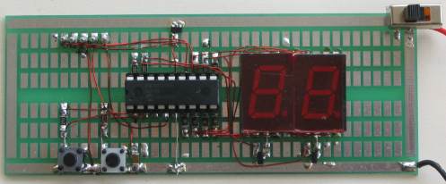
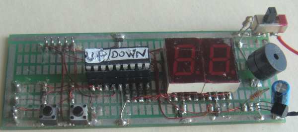
Photo of the 2-Digit Up/Down
Counter
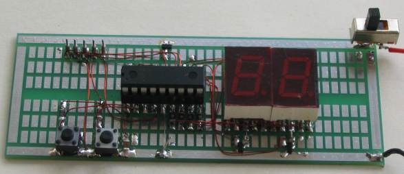
2 Digit up/down COUNTER
The experimenter PC Board shows
the five "In Circuit Programming" pins and a diode on the positive rail to
drop the 6v supply to 5.4v. The board also has a 100n surface mount
capacitor and two surface-mount transistors. The Up/Down buttons have
22k resistors.
TESTING THE CIRCUIT
Check the circuit by removing the chip and taking pins 6 and 18 to the
5v rail
ad make sure segment "A" illuminates. Do the same for all the other
segments.
The circuit diagram does not have any voltages marked on it as the
circuit is DIGITAL.
All the "lines" or "wires" or pins of a microcontroller will have rail
voltage (5v) on them when they are HIGH and when you come to a resistor,
the resistor will drop a certain voltage. The voltage it will drop will
be the difference between rail voltage and the voltage developed across
the component it is driving. If it is driving a LED, the LED will drop a
characteristic voltage of between 1.7v and 3.6v, depending on the
colour.
If the component is a transistor, the voltage developed between the base
and emitter will be about 0.7v.
;**************************************************************** ;* 2 Digit UP / Down Counter 17/6/2009 ;Port B drives two 7 segment displays ;Up Sw on RA2 Down Sw on RA3 ;"Units" drive on RA0 "Tens" drive on RA1 ;* * ;**************************************************************** list P = 16F628A ;microcontroller include |
If you want to suppress (remove) the first
"0" when the digits are 1, 2, 3, etc, here are the lines of code to add:
In the files section, add
|
In Main, add the following lines shown in BOLD:
Main	btfss	portA,2		;test switch-press for UP
	call	Up		;UP switch pressed
	btfss	portA,3		;test switch-press for Down
	call	Dwn		;Down switch pressed
        movlw   b'00111111'     ;binary for "0" on the display
        movwf   compare         ;put the value into compare
	movlw	b'00000001'	;Make RA0 HIGH for units drive
	movwf	portA
	movf	units,f		;copy unit value into w
	call	table		;unit display value will return in w
	movwf	portB		;output units value
	call	D_10mS		;call delay
	clrf	portB		;clear display
	movlw	b'00000010'	;Make RA1 HIGH for tens drive
	movwf	portA
	movf	tens,f		;copy tens value into w
	call	table		;tens display value will return in w
        subwf   compare,1
        btfsc   03,2            ;test zero flag for match
        movlw   0               ;remove the zero on the display
	movwf	portB		;output tens value
	call	D_10mS		;call delay
	clrf	portB		;clear display
	btfsc	portA,2		;bit will be zero when sw is pressed
	bcf	Sw_Flag,2
	btfsc	portA,3		;bit will be zero when sw is pressed
	bcf	Sw_Flag,3
	goto	Main

END |
The program above uses very simple instructions and it is very easy to
see how each line of code works. The only Boolean instruction is xorwf
and this is an ex-or instruction
(exclusive-or) which means two files are compared with each
bit in one file compared with the same bit in the other file.
The result is "1" when one
(and only one) of the numbers is "1." XOR
detects a MATCH. If two identical numbers are compared,
the answer for say the lowest bit will be
"0" because only one of the numbers must be "1." If both files contain
the same value, the result of the XOR is "0."
We now look at file 03, (the Status file) and check bit 2. This is the zero bit. The
result of the XOR instruction is "0" and thus the zero bit is SET.
This is the the most complex of the instructions used in this program.
Now we come to a program written by a PROGRAMMER.
It performs the same as the program above and has the same number of
instructions, but it contains a lot more Boolean instructions and this
makes it a lot harder to understand.
However it is very interesting to see how to program at the "next level
of understanding," and we will cover some of the features (these are
located after the program).
If you use any of the following .asm files and find they fail to produce
a .hex file, make sure you have the .inc file in the same folder as the
.asm.
P16F628.INC
P16F628A.INC
To add RESET to the up/down counter, add the following instructions:
SetUp	bsf	status,rp0
	movlw	b'00011100'	;Make RA0,1 out   RA2,3,4 in
Put reset on RA4 pin3 put 22k to positive and the switch between pin3 and 0v. When sw is pressed the input will go low. in main, the least few lines will bebcf Sw_Flag,2 ;button not pressed. Clear Up flag bcf Sw_Flag,7 ;Clear Up repeat flag clrf FastCount btfss portA,4 ;test reset goto SetUp goto Main END
;******************************************************************
;  2-Digit Up/Dn Counter, Isochronous Loop Example
;           Isochronous - to occur at equal time intervals.       *
;******************************************************************

        processor PIC16F628
        include "p16f628.inc"
        errorlevel -302

       __Config _cp_off & _lvp_off & _pwrte_on &
		_wdt_off & _intRC_osc_noclkout & _mclre_off

;code protection - off
;low-voltage programming - off
;power-up timer -  on
;watchdog timer - off
;use internal RC for 4MHz - all pins for in-out

ones    equ     0x20            ; 0..9
tens    equ     0x21            ; 0..9
number  equ     0x22            ; 00..99
swlatch equ     0x23            ; switch state latch variable
DelayHi equ     0x24            ; DelayCy() subsystem variable

#define DnSw    3               ; RA3

;******************************************************************
;
;  DelayCy() subsystem macro generates four instructions
;
        radix   dec
clock   equ     8               ; clock frequency in Megahertz
usecs   equ     clock/4         ; cycles/microsecond multiplier
msecs   equ     usecs*1000      ; cycles/millisecond multiplier

DelayCy macro   delay           ; 11..327690 cycle range
        movlw   high((delay-11)/5)+1
        movwf   DelayHi
        movlw   low ((delay-11)/5)
        call    uDelay-((delay-11)%5)
        endm

;******************************************************************
;
;  init hardware and program variables
;
        org     0x000
Init
        bsf     STATUS,RP0      ; bank 1
        movlw	07h		;turn comparators off and enable
	movwf	cmcon		;    pins for I/O functions
        movlw   b'00001100'     ;
        movwf   TRISA           ; RA3-RA2 inputs, others outputs
        clrf    TRISB           ; portb all outputs
        bcf     STATUS,RP0      ; bank 0
        clrf    PORTB           ; clear portb output latches
        movlw   b'00000001'     ; digit select bits (RA1-RA0)
        movwf   PORTA           ; select the 'ones' display
        clrf    swlatch         ; clear switch state latch
        clrf    ones            ; clear 'ones'
        clrf    tens            ; clear 'tens'
        clrf    number          ; number = 00
;
;  isochronous 8 msec main program loop (62.5Hz refresh rate)
;
Main    clrf    PORTB           ; blank the display
        movf    PORTA,W         ;
        xorlw   b'00000011'     ; flip digit select bits
        movwf   PORTA           ;
        movf    tens,W          ; WREG = tens, 0..9
        btfss   PORTA,1         ; display tens? yes, skip, else
        movf    ones,W          ; WREG = ones, 0..9
        call    segtbl          ; get segment data
        movwf   PORTB           ; display new digit
TstSw   comf    PORTA,W         ; sample active low switches
        andlw   b'00001100'     ; on RA3 and RA2 pins
        xorwf   swlatch,W       ; changes (press or release)
        xorwf   swlatch,F       ; update switch state latch
        andwf   swlatch,W       ; filter out "new release" bits
        bnz     Bump            ; branch on a "new press", else
        DelayCy(8*msecs-23)     ; precise 8 msec loop timing
        goto    Main            ;
;
;  bump 'number' up or down with limit checking
;
Bump    andlw   1<<DnSw         ; the "Dn" switch?
        skpz                    ; no, skip (WREG=0), else
        movlw   -2              ; WREG = -2 (dn)
        addlw   1               ; WREG = 1 (up) or -1 (dn)
        addwf   number,F        ; number++ or number--
        movf    number,W        ; WREG = number = -1..100
        xorlw   100             ; test upper limit
        skpnz                   ; upper limit? no, skip, else
        decf    number,F        ; reset to 99
        btfsc   number,7        ; lower limit? no, skip, else
        incf    number,F        ; reset to 00
        movf    number,W        ; WREG = number = 00..99
;
;  setup 'tens' and 'ones' for next loop
;
        clrf    tens            ; isochronous bin2bcd routine
        addlw   -80             ; W = W - 80
        rlf     tens,F          ; shift in 2^3*10 bit
        btfss   tens,0          ; borrow? no, skip, else
        addlw   80              ; W = W + 80
        addlw   -40             ; W = W - 40
        rlf     tens,F          ; shift in 2^2*10 bit
        btfss   tens,0          ; borrow? no, skip, else
        addlw   40              ; W = W + 40
        addlw   -20             ; W = W - 20
        rlf     tens,F          ; shift in 2^1*10 bit
        btfss   tens,0          ; borrow? no, skip, else
        addlw   20              ; W = W + 20
        addlw   -10             ; W = W - 10, now W = "ones"
        rlf     tens,F          ; shift in 2^0*10 bit
        btfss   tens,0          ; borrow? no, skip, else
        addlw   10              ; W = W + 10, now W = "ones"
        movwf   ones            ; save "ones"
        DelayCy(8*msecs-54)     ; precise 8 msec loop timing
        goto    Main            ;
;
;  segment data table (caveat, non-boundary tolerant)
;
segtbl
        addwf      PCL,F
        retlw      b'00111111'     ; "0"   -|F|E|D|C|B|A
        retlw      b'00000110'     ; "1"   -|-|-|-|C|B|-
        retlw      b'01011011'     ; "2"   G|-|E|D|-|B|A
        retlw      b'01001111'     ; "3"   G|-|-|D|C|B|A
        retlw      b'01100110'     ; "4"   G|F|-|-|C|B|-
        retlw      b'01101101'     ; "5"   G|F|-|D|C|-|A
        retlw      b'01111101'     ; "6"   G|F|E|D|C|-|A
        retlw      b'00000111'     ; "7"   -|-|-|-|C|B|A
        retlw      b'01111111'     ; "8"   G|F|E|D|C|B|A
        retlw      b'01101111'     ; "9"   G|F|-|D|C|B|A
;
; DelayCy() subsystem 16-bit timing subroutine
;
        nop                     ; entry for (delay-11)%5 == 4
        nop                     ; entry for (delay-11)%5 == 3
        nop                     ; entry for (delay-11)%5 == 2
        nop                     ; entry for (delay-11)%5 == 1
uDelay  addlw   -1              ; subtract "loop" cycle time
        skpc                    ; borrow? no, skip, else
        decfsz  DelayHi,F       ; done?  yes, skip, else
        goto    uDelay          ; do another loop
        retlw	00              ;

end |
The following instructions test the buttons and only go to the
increment/decrement routine (Bump) when a change in the value of the switches has
been detected.
On the first pass of the program, the micro complements the value of the
input port, (PortA) and loads it in to w. The instruction could have
been movwf PORTA,w and the following instruction would need to be andlw b'11110011'
to produce the same result. The instruction comf changes all "0's" to
"1's" and all "1's" to "0's." This project
uses "negative logic." This means the input line is "active" when LOW.
If no buttons are pressed, the reading on RA2 and RA3 will be "1" and
"1." The result of comf PORTA will be:
xxxx00xx where "x" is not assigned as an input bit.
The instruction: andlw b'00001100' is called a "masking
operation." All the bits except bit 2 and 3 are masked or "removed" from
the result.
When xxxx00xx is AND'ed with 00001100 the result is: aaaa00aa in the w register, where
"a" is not taken into account as we have only allowed bits 2 and 3 to
"enter the equation."
If the UP button is pressed, bit 2 will be detected as "0" and the result of comf PORTA will be:
xxxx01xx and the result of andlw b'00001100' will be xxxx01xx in the w register.
swlatch is a flag file for the switches. It is initially cleared and the
result of xorwf swlatch,w will be: xxxx00xx in the "w" file.
The instruction: xorwf swlatch,F does the Boolean XOR
operation on xxxx00xx in the "w" file and 00000000 in the swlatch file
and places the result: 00000000 in the swlatch file.
The instruction: andwf swlatch,W performs the Boolean AND
operation on: 00000000 in the w file AND 00000000 in the swlatch
file and places the result: 00000000 in w. The micro looks at the
zero bit in the STATUS file and it the result is zero, the bit will be
SET. The instruction bnz causes the micro to go the Bump if the zero bit
is not set. The zero bit is not set and thus the micro does not go to
Bump.
TstSw   comf    PORTA,W         ; sample active low switches
        andlw   b'00001100'     ; on RA3 and RA2 pins
        xorwf   swlatch,W       ; changes (press or release)
        xorwf   swlatch,F       ; update switch state latch
        andwf   swlatch,W       ; filter out "new release" bits
        bnz     Bump            ; branch on a "new press", else
|
The clever part of these 6 instructions is this: The
micro will only branch on the first detection of a button being pressed.
We will now look at how the first detection is created, but it will take
a lot of investigation to see how the Boolean operations perform the
task:
If the UP button is pressed (RA2 - bit 2), the input data will be xxxx10xx
The result of comf PORTA will be:
xxxx01xx and this will be stored in w.
andlw b'00001100' will AND xxxx01xx with
00001100 to get 00000100 in w.
xorwf swlatch,W will XOR 00000100 in w with
00000000 in swlatch to get 00000100 in w.
xorwf swlatch,F will XOR 00000100 in w with
00000000 in swlatch to get 00000100 in swlatch file.
andwf swlatch,W will AND 00000100 in w with 00000100
in swlatch to get 00000100 in w.
bnz Bump will look at the zero flag
in the STATUS file. This flag will not be set and thus the micro will
jump to the sub-routine Bump.
If the button is still pressed when the micro executes: TstSw the
second time, we will see what happens:
The result of comf PORTA will be:
xxxx01xx and this will be stored in w.
andlw b'00001100' will AND xxxx01xx with
00001100 to get 00000100 in w.
xorwf swlatch,W will XOR 00000100 in w with 00000100
in swlatch to get 00000000 in w.
xorwf swlatch,F will XOR 00000000 in w with
00000100 in swlatch to get 00000100 in swlatch file.
andwf swlatch,W will AND 00000000 in w with 00000100
in swlatch to get 00000000 in w.
bnz Bump will look at the zero flag
in the STATUS file. This flag will be set and thus the micro will not
jump to the sub-routine Bump.
If the button is released when the micro executes: TstSw we will
see how the swlatch file is changed to: 00000000.
If no buttons are pressed, the reading on port A will be: xxxx11xx
The result of comf PORTA will be:
xxxx00xx and this will be stored in w.
andlw b'00001100' will AND xxxx00xx with
00001100 to get 00000000 in w.
xorwf swlatch,W will XOR 00000000 in w with 00000100
in swlatch to get 00000100 in w.
xorwf swlatch,F will XOR 00000100 in w with
00000100 in swlatch to get 00000000 in swlatch file.
andwf swlatch,W will AND 00000000 in w with 00000000
in swlatch to get 00000000 in w.
bnz Bump will look at the zero flag
in the STATUS file. This flag will be set and thus the micro will not
jump to the sub-routine Bump. And the swlatch file will be changed to
00000000.
The Bump sub-routine
The Bump sub-routine detects
If Up button is pressed, "w" will enter Bump sub-routine with: 00000100.
If Down button is pressed, "w" will enter Bump sub-routine with:
00001000
Bump    andlw   1<<DnSw         ; the "Dn" switch?
        skpz                    ; no, skip (WREG=0), else
        movlw   -2              ; WREG = -2 (dn)
        addlw   1               ; WREG = 1 (up) or -1 (dn)
        addwf   number,F        ; number++ or number--
        movf    number,W        ; WREG = number = -1..100
        xorlw   100             ; test upper limit
        skpnz                   ; upper limit? no, skip, else
        decf    number,F        ; reset to 99
        btfsc   number,7        ; lower limit? no, skip, else
        incf    number,F        ; reset to 00
        movf    number,W        ; WREG = number = 00..99
|
If the UP button is pressed, the result of the first
instruction will produce w = 00000000. The zero flag will be SET
and the micro will execute the instruction: addlw 1
- "One" will be added to "w"
addwf number,F will increment the number file.
movf number,W the value in the number
file will be copied to "w"
xorlw 100 The value in w will be
XOR'ed with 100. The XOR operation detects a match.
Since each binary
digit will be the same (i.e. either a 0 or 1) the result will be
0000 0000. The result will set the zero flag in the status (03)
file and by testing bit 2 (the Z flag) you can skip when SET.
decf number,F The number file will be
detected as 100. Decrement it to 99.
btfsc number,7 If the number file is
decremented below zero, it rolls-over to 0FFh (255) and bit 7 is
tested to see if it is SET.
incf number,F The number
file is incremented (rolled over) from 256 to 000.
movf number,W The number file is copied
to w.
The Binary to Binary Coded
Decimal Routine
This routine is so complex
that I am not going to explain it.
	; isochronous bin2bcd routine

	clrf    tens
        addlw   -80             ; W = W - 80
        rlf     tens,F          ; shift in 2^3*10 bit
        btfss   tens,0          ; borrow? no, skip, else
        addlw   80              ; W = W + 80
        addlw   -40             ; W = W - 40
        rlf     tens,F          ; shift in 2^2*10 bit
        btfss   tens,0          ; borrow? no, skip, else
        addlw   40              ; W = W + 40
        addlw   -20             ; W = W - 20
        rlf     tens,F          ; shift in 2^1*10 bit
        btfss   tens,0          ; borrow? no, skip, else
        addlw   20              ; W = W + 20
        addlw   -10             ; W = W - 10, now W = "ones"
        rlf     tens,F          ; shift in 2^0*10 bit
        btfss   tens,0          ; borrow? no, skip, else
        addlw   10              ; W = W + 10, now W = "ones"
        movwf   ones            ; save "ones"
        DelayCy(8*msecs-54)     ; precise 8 msec loop timing
        goto    Main            ;
|
Here is a shorter Binary to Binary Coded Decimal Routine:
; Convert a binary number into two packed BCD digits ; ON ENTRY: ; w register has binary value in range 0 t o 9 9 ; ON EXIT: ; output variables bcdLow and bcdHigh contain two ; BCD digits ; w contains two packed BCD digits ; Routine logic: ; The value 10 is subtracted from the source operand ; until the reminder is < 0 (carry cleared). The number ; of subtractions is the high-order BCD digit. 10 is ; then added back to the subtrahend to compensate ; for the last subtraction. The final remainder is the ; low-order BCD digit ; Variables: ; inNum storage for source operand ; bcdHigh storage for high-order nibble ; bcdLow storage for low-order nibble ; thisDig Digit counter bin2bcd: movwf inNum ; Save copy of source value clrf bcdHigh ; Clear storage clrf bcdLow clrf thisDig min10: movlw .10 subwf inNum,f ; Subtract 10 btfsc STATUS,C ; Did subtract overflow? goto sum10 ; No. Count subtraction goto fin10 sum10: incf thisDig,f ;increment digit counter goto min10 ; Store 10th digit fin10: movlw .10 addwf inNum,f ; Adjust for last subtract movf thisDig,w ; get digit counter movwf bcdHigh ; Store it ; Calculate and store low-order BCD digit movf inNum,w ; Store units value movwf bcdLow ; Store digit ; Combine both digits swapf bcdHigh,w ; High nibble to HOBs iorwf bcdLow,w ; ORin low nibble retlw 00 |
Here is a simpler Binary to Binary Coded Decimal Routine:
;  Binary-to-Decimal, 00..99
;
         radix   dec
btod99
         clrf    temp            ; W = 0x00..0x63, 0..99 input
         decf    temp,F          ; preset temp to -1
sub10    incf    temp,F          ; unconditionally
         addlw   -10             ; subtract 10. borrow?
         btfsc   status,0        ; no, test carry bit
	 goto	 sub10
         addlw   10              ; fix 'ones' in Wreg
         swapf   temp,F          ; put 'tens' in left nibble
         iorwf   temp,W          ; W = packed bcd 0x00..0x99
retlw 00 |
Delay Routine
The delay sub-routine is quite complex however the following instructions form part and these will be discussed:
addlw -1 This instruction subtracts "1" from "w" (the PIC chip does not have a subtract literal from w, just a subtract w from literal.) W must have a value before entering this delay.
skpc This instruction skips the next instruction if the Carry (in the status file) (03,0) is SET. The Carry is SET when the result of an operation is more than 0ffh or less than zero. The equivalent instruction is: btfss 03,0 or btfss status,0
If w enters the delay with 0ffh, it will produce 256 loops by jumping over decfsz DelayHi,F and carrying out the instruction: goto uDelay.
When the carry is SET, the micro goes to the instruction: decfsz DelayHi,F and decrements the DelayHi file. It then performs another 256 loops.
When DelayHi file reaches zero, the micro returns. If w does not have a pre-value, only the first loop will be shorter. DelayHi file must have a value as this file determines the length of Delay routine.
uDelay  addlw   -1              ; subtract "loop" cycle time
        skpc                    ; borrow? no, skip, else
        decfsz  DelayHi,F       ; done?  yes, skip, else
        goto    uDelay          ; do another loop
        retlw	00
|
Conclusion
From the above coverage of
the two programs you can see the enormous difference in
understanding required to follow some of the Boolean operations.
Since both programs occupy the same number of instructions, I do
not see the need to introduce complex routines.
Things are wonderful when they are working but if something
fails to produce a result as expected, you will have two levels
of complexity to sort-through if you use Boolean instructions.
In addition to this, you need to comment each line, not only
with details of what the instruction is doing, but WHY the
instruction has been chosen.
This is very important so that you can come back months later
and understand how and why a routine works and how it can be
altered and adjusted.
Adding ALARM
The program can be
modified to produce an alarm when the count reaches "00."
The files for this are:
Up/DwnAlarm00.asm
Up/DwnAlarm00.hex
An active piezo buzzer is added to portA,6 (pin 15) as
shown in the following diagram:
Alarm buzzer sounds when
00 on Displays
Going Further
This program/project can be
modified to carry out all sorts of tasks. One constructor wanted
a Quiz Score with 3 single displays, three contestant switches
and a reset button. The adjudicator could increase the
individual score or decrease the score according to the answer.
This project could be adapted to this application.
Another reader wanted to count from 35 to 80 and cycle around
these two values. Again, this can be done by simply changing a
few lines of code.
You can add a relay, buzzer, set of LEDs, globes and actuators
to the project to create a valuable piece of industrial
equipment.
Fast Increment
Another feature that can be
added to the counter is fast-forward. Although it is not needed
for this project, it is a sub-routine that can be added to other
designs.
The way it works is this.
Each time the micro executes the FastUp sub-routine, a file is
incremented. When the file reaches 100, the display is
incremented at a rate of 5Hz.
The delay for the multiplexing routine is 10mS per display. This
makes a total of 20mS. The counter detects 100 so the time
before fast-increment occurs = 20mS x 100 = 2,000mS = 2 seconds.
FastUp sub-routine also needs a flag to detect when the fast
increment is occurring. This is bit 7 of Sw_Flag. After the 2
second timing has occurred, the program increments the FastCount
file for 5 loops to produce the fast increment function.
Here are the files:
2DigitFastUp.asm
2DigitFastUp.hex
2DigitFastUp.txt (.asm)
2DigitFastUp-h.txt (.hex)
If you use any of the following .asm files and find they fail to produce
a .hex file, make sure you have the .inc file in the same folder as the
.asm.
P16F628.INC
P16F628A.INC
To add RESET to the up/down counter, add the following instructions:
SetUp bsf status,rp0 movlw b'00011100' ;Make RA0,1 out RA2,3,4 in Put reset on RA4 pin3 put 22k to positive and the switch between pin3 and 0v. When sw is pressed the input will go low. in main, the least few lines will bebcf Sw_Flag,2 ;button not pressed. Clear Up flag bcf Sw_Flag,7 ;Clear Up repeat flag clrf FastCount btfss portA,4 ;test reset goto SetUp goto Main END
;**************************************************************** ;* Started 18/6/2009 ;2 Digit UP / Down Counter with FastCount after 2secs ;Port B drives 7 segment display ;Up sw on RA2 Down on RA3 ;Units drive on RA0 Tens drive on RA1 * ;* * ;**************************************************************** list P = 16F628 ;microcontroller include |
Secret Functions
This project can be extended to have
"Secret Functions" that are accessed when the project is turned
on.
By pressing the "Up" button and turning the project on, the
project will turn into a "DICE PROJECT" and show a random number
from 1 to 6 when the Up button is pressed.
When the "Down" button is pressed and the project is turned on,
it will randomly show a number from 00 to 99 when the Up button
is pressed.
Firstly we will describe the instructions that look at the
buttons when the project is turned on.
The following instructions are added to the SetUp routine:
SetUp . . . . . . . . . . . . goto AAA ;Button A detected for DICE (detects LOW) btfsc portA,3 goto Main clrf Count goto Random ;Button B detected |
These programs are covered on page 2:
18/6/09